

Feasibility of Atlas Pedicle Screw Fixation Perpendicular to the Coronal Plane-A 3D Anatomic Analysis
- PMID: 33525954
- PMCID: PMC9394002
- DOI: 10.1177/2192568220980715
Feasibility of Atlas Pedicle Screw Fixation Perpendicular to the Coronal Plane-A 3D Anatomic Analysis
Abstract
Study design: An anatomic analysis.
Objective: To investigate the feasibility of the ideal atlas pedicle screw trajectory perpendicular to the coronal plane via atlas digital 3D reconstruction.
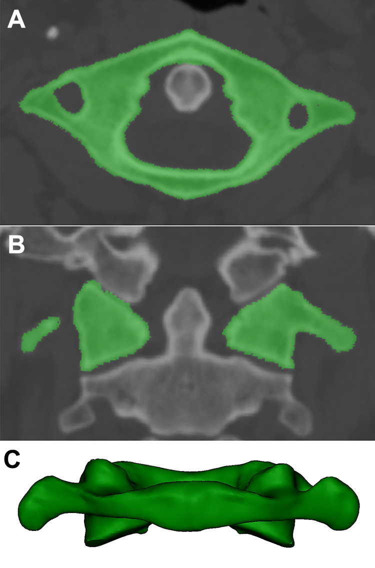
Methods: One hundred adult atlases were evaluated in this study. The projection of the corridor for atlas pedicle screw fixation perpendicular to the coronal plane was quickly obtained using the perspective model of 3D reconstruction, and the area, long axis, short axis and width of the pedicle corridor were measured. The inner trajectory was near the lateral wall of the pedicle, and the center of the corridor was point A. The lateral trajectory was near the lateral wall of the transverse foramen, and the center of the trajectory was point C. The midpoint of A and C was B. The length of the inner, middle and lateral trajectorys were measured. The distances from points A, B and C to the posterior tubercle of the atlas and safety swing angle were measured.
Results: From the dorsal view, the pedicle corridor was fitted into an ellipse with an average long axis of 13.6 mm, an average short axis of 5.2 mm, and an average area of 56.3 mm2. From the axial view, the pedicle corridor had an average width of 9.4 mm. The average lengths of the inner trajectory, middle trajectory and lateral trajectory were 31.7 mm, 28.7 mm and 25.1 mm, respectively; The average distances from the posterior tubercle to points A, B and C were 17.1 mm, 20.8 mm and 24.5 mm, respectively. The average swing angles from points A, B and C were 16.1°, 25.5°, and 28.1°, respectively.
Conclusion: Atlas pedicle screw fixation perpendicular to the coronal plane is feasible for almost all the volunteers. Pedicle screws close to the pedicle lateral wall of the atlas posterior arch perpendicular to the coronal plane is an advanced technique that is easy to master.
Keywords: 3D reconstruction; anatomy; atlas; pedicle screws.
Conflict of interest statement
Figures


References
-
- Lu Y, Lee Y P, Bhatia NN, Lee TQ. Biomechanical comparison of C1 lateral mass—C2 short pedicle screw—C3 lateral mass screw-rod construct versus Goel-Harms fixation for atlantoaxial instability. Spine. 2018;44(7):e393–399. doi:10.1097/BRS.0000000000002868 - PubMed
-
- Ma XY, Yin QS, Wu ZH, et al. C1 pedicle screws versus C1 lateral mass screws: comparisons of pullout strengths and biomechanical stabilities. Spine. 2009;34(4):371–377. doi:10.1097/BRS.0b013e318193a21b - PubMed
-
- Hu Y, Kepler CK, Albert TJ, et al. Accuracy and complications associated with the freehand C1 lateral mass screw fixation technique: a radiographic and clinical assessment. J Neurosurg Spine. 2013;18(4):372–377. doi:10.3171/2013.1.SPINE12724 - PubMed
-
- Ma XY, Yin QS, Wu ZH, Xia H, Liu JF, Zhong SZ. Anatomic considerations for the pedicle screw placement in the first cervical vertebra. Spine. 2005;30(13):1519–1523. doi:10.1097/01.brs.0000168546.17788.49 - PubMed
LinkOut - more resources
Full Text Sources
Other Literature Sources
