

Electromagnetic simulation of a 16-channel head transceiver at 7 T using circuit-spatial optimization
- PMID: 33533500
- PMCID: PMC8124020
- DOI: 10.1002/mrm.28672
Electromagnetic simulation of a 16-channel head transceiver at 7 T using circuit-spatial optimization
Abstract
Purpose: With increased interest in parallel transmission in ultrahigh-field MRI, methods are needed to correctly calculate the S-parameters and complex field maps of the parallel transmission coil. We present S-parameters paired with spatial field optimization to fully simulate a double-row 16-element transceiver array for brain MRI at 7 T.
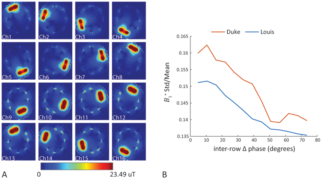
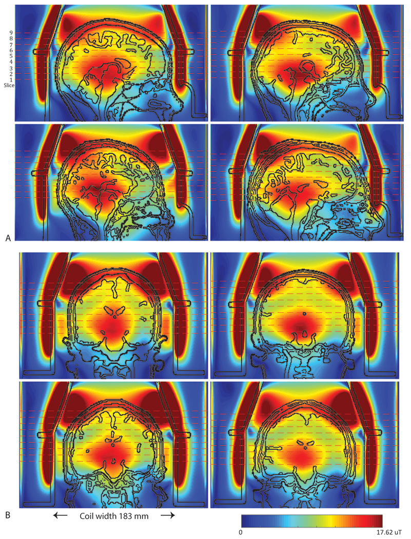
Methods: We implemented a closed-form equation of the coil S-parameters and overall spatial field. We minimized a cost function, consisting of coil S-parameters and the homogeneity in brain tissue, by optimizing transceiver components, including matching, decoupling circuits, and lumped capacitors. With this, we are able to compare the in silico results determined with and without homogeneity weighting. Using the known voltage range from the host console, we reconstructed the maps of the array and performed RF shimming with four realistic head models.
Results: As performed with homogeneity weighting, the optimized coil circuit components were highly consistent over the four heads, producing well-tuned, matched, and decoupled coils. The mean peak forward powers and statistics for the head models are consistent with in vivo human results (N = 8). There are systematic differences in the transceiver components as optimized with or without homogeneity weighting, resulting in an improvement of 28.4 ± 7.5% in homogeneity with a small 1.9 ± 1.5% decline in power efficiency.
Conclusion: This co-simulation methodology accurately simulates the transceiver, predicting consistent S-parameters, component values, and field. The RF shimming of the calculated field maps match the in vivo performance.
Keywords: EM simulation; RF shimming; co-simulation; parallel transmission; transformer decoupling; ultrahigh-field MRI.
© 2021 International Society for Magnetic Resonance in Medicine.
Figures


Similar articles
-
Double-row 16-element folded-end dipole transceiver array for 3D RF shimming of the whole human brain at 9.4 T.NMR Biomed. 2023 Oct;36(10):e4981. doi: 10.1002/nbm.4981. Epub 2023 Jun 10. NMR Biomed. 2023. PMID: 37173759
-
Magnetic field probe-based co-simulation method for irregular volume-type inductively coupled wireless MRI radiofrequency coils.Magn Reson Imaging. 2025 Apr;117:110330. doi: 10.1016/j.mri.2025.110330. Epub 2025 Jan 21. Magn Reson Imaging. 2025. PMID: 39848453
-
Hairpin RF resonators for MR imaging transceiver arrays with high inter-channel isolation and B1 efficiency at ultrahigh field 7 T.J Magn Reson. 2022 Dec;345:107321. doi: 10.1016/j.jmr.2022.107321. Epub 2022 Oct 29. J Magn Reson. 2022. PMID: 36335877 Free PMC article.
-
Simultaneous whole-brain and cervical spine imaging at 7 T using a neurovascular head and neck coil with 8-channel transceiver array and 56-channel receiver array.Magn Reson Med. 2025 Jul;94(1):386-400. doi: 10.1002/mrm.30450. Epub 2025 Jan 29. Magn Reson Med. 2025. PMID: 39887456 Free PMC article.
-
Electromagnetic and RF pulse design simulation based optimization of an eight-channel loop array for 11.7T brain imaging.Magn Reson Med. 2023 Aug;90(2):770-783. doi: 10.1002/mrm.29654. Epub 2023 Mar 31. Magn Reson Med. 2023. PMID: 36999747
Cited by
-
Large improvement in RF magnetic fields and imaging SNR with whole-head high-permittivity slurry helmet for human-brain MRI applications at 7 T.Magn Reson Med. 2025 Mar;93(3):1205-1219. doi: 10.1002/mrm.30350. Epub 2024 Oct 24. Magn Reson Med. 2025. PMID: 39449244 Free PMC article.
-
Bench to bore ramifications of inter-subject head differences on RF shimming and specific absorption rates at 7T.Magn Reson Imaging. 2022 Oct;92:187-196. doi: 10.1016/j.mri.2022.07.009. Epub 2022 Jul 13. Magn Reson Imaging. 2022. PMID: 35842192 Free PMC article.
-
Quantitative mapping of key glucose metabolic rates in the human brain using dynamic deuterium magnetic resonance spectroscopic imaging.PNAS Nexus. 2025 Mar 3;4(3):pgaf072. doi: 10.1093/pnasnexus/pgaf072. eCollection 2025 Mar. PNAS Nexus. 2025. PMID: 40109558 Free PMC article.
-
Simulation Validation of an 8-Channel Parallel-Transmit Dipole Array on an Infant Phantom: Including RF Losses for Robust Correlation with Experimental Results.Sensors (Basel). 2024 Apr 1;24(7):2254. doi: 10.3390/s24072254. Sensors (Basel). 2024. PMID: 38610465 Free PMC article.
-
Imaging the Internal Auditory Canal with an 8 × 2 Transceiver Array Head Coil at 7T.AJNR Am J Neuroradiol. 2025 Apr 2;46(4):852-858. doi: 10.3174/ajnr.A8569. AJNR Am J Neuroradiol. 2025. PMID: 40147834
References
Publication types
MeSH terms
Grants and funding
LinkOut - more resources
Full Text Sources
Other Literature Sources
Medical
Research Materials
