. 2020 Dec 14;17(24):9358.
doi: 10.3390/ijerph17249358.

Validation of an Intra-Oral Scan Method Versus Cone Beam Computed Tomography Superimposition to Assess the Accuracy between Planned and Achieved Dental Implants: A Randomized In Vitro Study

Affiliations

Validation of an Intra-Oral Scan Method Versus Cone Beam Computed Tomography Superimposition to Assess the Accuracy between Planned and Achieved Dental Implants: A Randomized In Vitro Study

Alessio Franchina et al. Int J Environ Res Public Health. .

Abstract

Computer aided implantology is the safest way to perform dental implants. The research of high accuracy represents a daily effort. The validated method to assess the accuracy of placed dental implants is the superimposition of a pre-operative and a post-operative cone beam computed tomography (CBCT) with planned and placed implants. This procedure is accountable for a biologic cost for the patient. To investigate alternative procedure for accuracy assessment, fifteen resin casts were printed. For each model, six implants were digitally planned and then placed following three different approaches: (a) template guided free hand, (b) static computer aided implantology (SCAI), and (c) dynamic computer aided implantology (DCAI). The placement accuracy of each implant was performed via two methods: the CBCT comparison described above and a matching between implant positions recovered from the original surgical plan with those obtained with a post-operative intraoral scan (IOS). Statistically significant mean differences between guided groups (SCAI and DCAI) and the free hand group were found at all considered deviations, while no differences resulted between the SCAI and DCAI approaches. Moreover, no mean statistically significant differences were found between CBCT and IOS assessment, confirming the validity of this new method.

Keywords: accuracy; dynamic computer aided implantology; dynamic navigation implantology; intra-oral scanning; static computer aided implantology; superimposition; surgical guides.


Conflict of interest statement

The authors declare no conflict of interest.

Figures

Figure 1
Figure 1
Fifteen marked identical resin models and the three surgical guides were manufactured to perform the study. Each model was coded according to randomization.
Figure 2
Figure 2
The fiducial marker device (NaviBite®, Biomax Spa, Italy) is helpful to align the STL files of the soft tissues and teeth with their own representation on DICOM files (a) and is customized using a silicon index material on both sides (b). A radiopaque marker is embedded in the center part of the device to be used, on both sides, for the STL-DICOM merging step, as shown in the 3D views (c,d).
Figure 3
Figure 3
The bone-teeth cone beam computed tomography (CBCT) baseline status (a) with merged STL files of soft tissues (b) and with the wax-up scan (c) was taken with an extra oral scanner and loaded into the surgical SCAI software to be used for prosthetic driven implant planning (d).
Figure 4
Figure 4
The planning software allows bone anatomy to be checked by three 2D windows (ac) and one 3D window (d). At each window, the view is adjustable in order to better represent the bone section in the other windows. The final implant setup is performed according to the standard guidelines on 2-dimensional views.
Figure 5
Figure 5
The stereolithographic surgical guide with PEEK sleeve embedded. It is important to note sleeves placed in the sites where SCAI protocol was planned and the wax-up shape of the guide for the remaining implant site.
Figure 6
Figure 6
The Navident desktop was divided into five windows. The 3D view shows the fiducial marker used and the overlapped STL file taken from an extra oral scan of the lower jaw (a). Four 2D windows (panorex (b), sagittal (c), cross-sectional (d), and axial (e)) allowed us to perform the implant planning. After wax-up, the STL file was overlapped above the original patient’s DICOM data, and a prosthetic driven implant planning was performed.
Figure 7
Figure 7
The tracer tool slides above the teeth for a 15 cm path to perform the required accuracy check.
Figure 8
Figure 8
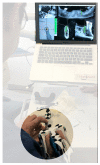
The unconventional way to prepare implant sites, following both the planned implant site and the drill advancement by an indirect screen view.
Figure 9
Figure 9
To perform the free hand (template guided) surgeries in the most accurate manner, the guides were perforated in the center of the occlusal plate of each selected site (a) and an attempt to be compliant with the project was done. Picture (b) shows a site with a sleeve and a dedicated bur performing the static SCAI approach.
Figure 10
Figure 10
The pre-op planning and post-op CBCT of the model overlapped to analyze implant deviations. A preliminary segmentation of both implants and jaws was performed (ad). The 3D objects of the jaws were hidden, leaving only 3D implants of both the pre-op and post-op scan (c). These implant positions and images were used to perform the deviation analysis.
Figure 11
Figure 11
The position of the achieved implants was carried out by scanning the original scan abutment (a) for digital workflow (Biomax spa, Vicenza, VI, Italy). The picture (b) shows the resulting 3D digital cast obtained by the IOS of the resin model used to perform the surgeries.
Figure 12
Figure 12
Simple bar charts (with confidence intervals) show the mean at coronal (mm), apex (mm), depth (mm), and angle (°) level among the three different approaches of implant placement.
Figure 13
Figure 13
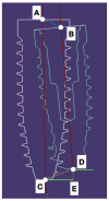
The reference points taken into account to assess deviations were the coronal (A,B) and the apical (C,D) deviation of the center part of the implant. The depth displacement (D,E) represented the final effect of the deviation on the final vertical position of the implant apex. The angular (AC,BD) deviations were also estimated.

References

    1. Adell R., Eriksson B., Lekholm U., Brånemark P.I., Jemt T. Long-term follow-up study of osseointegrated implants in the treatment of totally edentulous jaws. Int. J. Oral Maxillofac. Implant. 1990;5:347–359. - PubMed
    1. Lang N.P., Pjetursson B.E., Tan K., Brägger U., Egger M., Zwahlen M. A systematic review of the survival and c omplication rates of fixed partial dentures (FPDs) after an observation period of at least 5 years. II. Combined tooth--implant-supported FPDs. Clin. Oral Implant. Res. 2004;15:643–653. doi: 10.1111/j.1600-0501.2004.01118.x. - DOI - PubMed
    1. Jemt T., Johansson J. Implant treatment in the edentulous maxillae: A 15-year follow-up study on 76 consecutive patients provided with fixed prostheses. Clin. Implant. Dent. Relat. Res. 2006;8:61–69. doi: 10.1111/j.1708-8208.2006.00003.x. - DOI - PubMed
    1. Wyatt C.C., Pharoah M.J. Imaging techniques and image interpretation for dental implant treatment. Int. J. Prosthodont. 1998;11:442–452. - PubMed
    1. Guerrero M.E., Jacobs R., Loubele M., Schutyser F., Suetens P., van Steenberghe D. State-of-the-art on cone beam CT imaging for preoperative planning of implant placement. Clin. Oral Investig. 2006;10:1–7. doi: 10.1007/s00784-005-0031-2. - DOI - PubMed

MeSH terms

Substances

LinkOut - more resources