

Improved 7 Tesla transmit field homogeneity with reduced electromagnetic power deposition using coupled Tic Tac Toe antennas
- PMID: 33564013
- PMCID: PMC7873125
- DOI: 10.1038/s41598-020-79807-9
Improved 7 Tesla transmit field homogeneity with reduced electromagnetic power deposition using coupled Tic Tac Toe antennas
Abstract
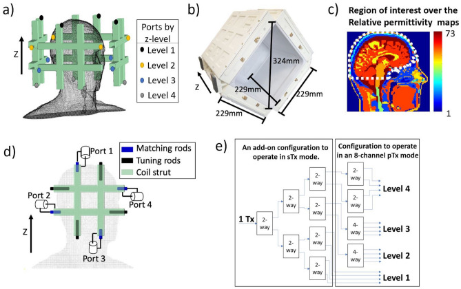
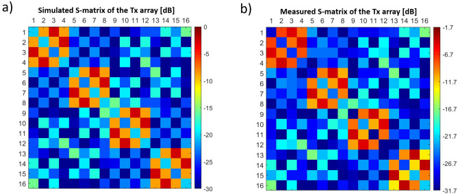
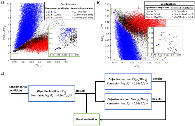
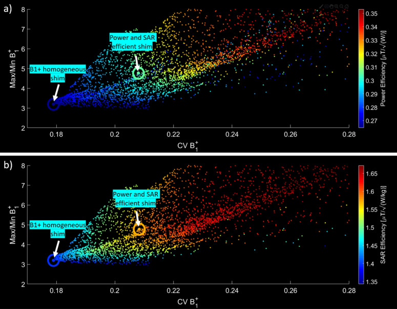
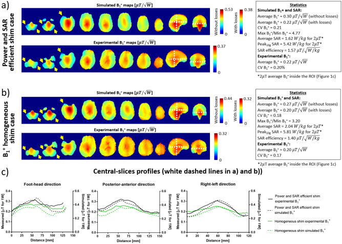
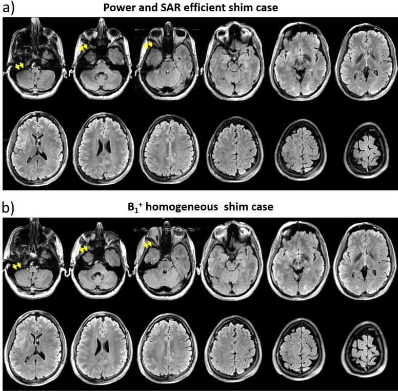
Recently cleared by the FDA, 7 Tesla (7 T) MRI is a rapidly growing technology that can provide higher resolution and enhanced contrast in human MRI images. However, the increased operational frequency (~ 297 MHz) hinders its full potential since it causes inhomogeneities in the images and increases the power deposition in the tissues. This work describes the optimization of an innovative radiofrequency (RF) head coil coupled design, named Tic Tac Toe, currently used in large scale human MRI scanning at 7 T; to date, this device was used in more than 1,300 neuro 7 T MRI scans. Electromagnetic simulations of the coil were performed using the finite-difference time-domain method. Numerical optimizations were used to combine the calculated electromagnetic fields produced by these antennas, based on the superposition principle, resulting in homogeneous magnetic field distributions at low levels of power deposition in the tissues. The simulations were validated in-vivo using the Tic Tac Toe RF head coil system on a 7 T MRI scanner.
Conflict of interest statement
The authors declare no competing interests.
Figures
Similar articles
-
In-vivo and numerical analysis of the eigenmodes produced by a multi-level Tic-Tac-Toe head transmit array for 7 Tesla MRI.PLoS One. 2018 Nov 27;13(11):e0206127. doi: 10.1371/journal.pone.0206127. eCollection 2018. PLoS One. 2018. PMID: 30481187 Free PMC article.
-
Dual optimization method of radiofrequency and quasistatic field simulations for reduction of eddy currents generated on 7T radiofrequency coil shielding.Magn Reson Med. 2015 Nov;74(5):1461-9. doi: 10.1002/mrm.25424. Epub 2014 Nov 3. Magn Reson Med. 2015. PMID: 25367703 Free PMC article.
-
A comprehensive electromagnetic evaluation of an MRI anthropomorphic head phantom.NMR Biomed. 2021 Mar;34(3):e4441. doi: 10.1002/nbm.4441. Epub 2020 Dec 22. NMR Biomed. 2021. PMID: 33354828 Free PMC article.
-
[3 Tesla MRI: successful results with higher field strengths].Radiologe. 2004 Jan;44(1):31-47. doi: 10.1007/s00117-003-1000-x. Radiologe. 2004. PMID: 14997868 Review. German.
-
Radiofrequency Coils for 7 Tesla MRI.Top Magn Reson Imaging. 2019 Jun;28(3):145-158. doi: 10.1097/RMR.0000000000000206. Top Magn Reson Imaging. 2019. PMID: 31188273 Review.
Cited by
-
RF shimming strategy for an open 60-channel RF transmit 7T MRI head coil for routine use on the single transmit mode.Magn Reson Med. 2025 Oct;94(4):1804-1816. doi: 10.1002/mrm.30563. Epub 2025 May 20. Magn Reson Med. 2025. PMID: 40391665 Free PMC article.
-
Independence-based causal discovery analysis reveals statistically non-significant regions to be functionally significant.bioRxiv [Preprint]. 2025 Jun 25:2025.06.19.660609. doi: 10.1101/2025.06.19.660609. bioRxiv. 2025. PMID: 40667378 Free PMC article. Preprint.
-
Aseptic, semi-sealed cranial chamber implants for chronic multi-channel neurochemical and electrophysiological neural recording in nonhuman primates.bioRxiv [Preprint]. 2025 Feb 11:2025.02.10.636943. doi: 10.1101/2025.02.10.636943. bioRxiv. 2025. Update in: J Neurosci Methods. 2025 Aug;420:110467. doi: 10.1016/j.jneumeth.2025.110467. PMID: 39990309 Free PMC article. Updated. Preprint.
-
Cross-Modality Image Translation of 3 Tesla Magnetic Resonance Imaging to 7 Tesla Using Generative Adversarial Networks.Hum Brain Mapp. 2025 Jun 15;46(9):e70246. doi: 10.1002/hbm.70246. Hum Brain Mapp. 2025. PMID: 40545512 Free PMC article.
-
Intermittent low-intensity and moderate-intensity exercise effects on cognition in community-dwelling older adults: a pilot study exploring biological mechanisms.Front Aging Neurosci. 2024 Oct 17;16:1432909. doi: 10.3389/fnagi.2024.1432909. eCollection 2024. Front Aging Neurosci. 2024. PMID: 39484365 Free PMC article.
References
Publication types
MeSH terms
Grants and funding
LinkOut - more resources
Full Text Sources
Other Literature Sources
Medical
