. 2021 Feb 18;16(2):e0246124.
doi: 10.1371/journal.pone.0246124. eCollection 2021.

Magnetic microparticle concentration and collection using a mechatronic magnetic ratcheting system

Affiliations

Magnetic microparticle concentration and collection using a mechatronic magnetic ratcheting system

Oladunni B Adeyiga et al. PLoS One. .

Abstract

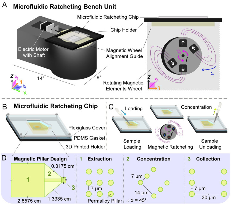
Magnetic ratcheting cytometry is a promising approach to separate magnetically-labeled cells and magnetic particles based on the quantity of magnetic material. We have previously reported on the ability of this technique to separate magnetically-labeled cells. Here, with a new chip design, containing high aspect ratio permalloy micropillar arrays, we demonstrate the ability of this technique to rapidly concentrate and collect superparamagnetic iron oxide particles. The platform consists of a mechatronic wheel used to generate and control a cycling external magnetic field that impinges on a "ratcheting chip." The ratcheting chip is created by electroplating a 2D array of high aspect ratio permalloy micropillars onto a glass slide, which is embedded in a thin polymer layer to create a planar surface above the micropillars. By varying magnetic field frequency and direction through wheel rotation rate and angle, we direct particle movement on chip. We explore the operating conditions for this system, identifying the effects of varying ratcheting frequency, along with time, on the dynamics and resulting concentration of these magnetic particles. We also demonstrate the ability of the system to rapidly direct the movement of superparamagnetic iron oxide particles of varying sizes. Using this technique, 2.8 μm, 500 nm, and 100 nm diameter superparamagnetic iron oxide particles, suspended within an aqueous fluid, were concentrated. We further define the ability of the system to concentrate 2.8 μm superparamagnetic iron oxide particles, present in a liquid suspension, into a small chip surface area footprint, achieving a 100-fold surface area concentration, and achieving a concentration factor greater than 200%. The achieved concentration factor of greater than 200% could be greatly increased by reducing the amount of liquid extracted at the chip outlet, which would increase the ability of achieving highly sensitive downstream analytical techniques. Magnetic ratcheting-based enrichment may be useful in isolating and concentrating subsets of magnetically-labeled cells for diagnostic automation.


Conflict of interest statement

The authors have read the journal’s policy and have the following competing interests: CM is an employee of Ferrologix, Inc. The authors would like to declare patent US10144911B2 associated with this research. This does not alter our adherence to PLOS ONE policies on sharing data and materials. There are no products in development or marketed products associated with this research.

Figures

Fig 1
Fig 1. Microfluidic magnetic ratcheting unit and chip.
A) An isometric drawing of the unit, which consists of a 3D printed unit base, a motorized unit, a rotating wheel of N52 grade rare Earth magnets arranged in a partial Halbach array, and enclosure which contains the microfluidic ratcheting chip. An enlarged illustration of the partial Halbach magnet array demonstrates the magnetic field generated by the wheel over multiple wheel rotation cycles. The wheel rotates in the y-z plane with frequency (f) that is established by the rotational velocity (ω), where ω = 2πf = dθ/dt. B) The microfluidic ratcheting chip is within an enclosure that also contains a Plexiglass cover, PDMS gasket, and 3D printed holder. C) Fluid processed on the chip surface is introduced into the chip inlet region and removed from the chip outlet region using a micropipetter. D) This chip design contains three regions, with different permalloy pillar array geometries.
Fig 2
Fig 2. Surface particle movement dynamics.
Illustrated magnetic particle movement dynamics; as the mechatronic wheel cycles, MPs translate across chip surface. The rotating wheel, which contains two N52 grade rare Earth magnets (2.5 cm x 2.5 cm x 1 cm) connected with two nonmagnetic metal bars, rotates around the x axis and generates surface magnetic potential energy wells. The width, b = 2.5 cm is shown as well as the depth, a = 1 cm. Shifting surface magnetic potential energy minima locations make rectified magnetic particle movement energetically favorable. Here, particle movement over the chip surface which has been planarized by a polystyrene layer is displayed in five stages, where, between stage 1 and stage 5, a particle is translated from one pillar to the next pillar, but not to the preceding pillar because this is energetically unfavorable. An illustration of the magnetic field generated over multiple wheel rotations is shown, along with a photo of the partial Halbach magnet array.
Fig 3
Fig 3. Simulation data plots.
A) Magnetic flux density contours from COMSOL® (COMSOL, Inc.) simulation data which has been displayed using MATLAB®. Demonstrated magnetic contours display chip surface magnetic flux density with the wheel position at position A, angle phi (ϕ) = 0° & 30°. High gradients in flux density correspond to regions where magnetic particles are phase locked as the external field cycles. In comparing displays for the two wheel positions, there is a difference in the angle of the field minima, in comparison to the magnetic pillar structures. These pillar structures represent the region of the chip where region 1 and region 2 meet. B) COMSOL Model. Using COMSOL, a 3D model displaying the geometry of the magnetic ratcheting chip was created. The displayed pillar structures represent the region of the chip where region 1 and region 2 meet. The chip contains permalloy pillars with 4 μm diameter, which are covered by a 1 μm thick polystyrene layer.
Fig 4
Fig 4. Concentration factors for experiments with 2.8 μm particles.
Using azimuth angle phi (φ) = 30°, CnFc (calculated using Eq 1) is shown to increase with A) ratcheting time and B) frequency for 2.8 μm particles. Mean CnFc for N = 3 trials with standard error calculation is displayed. Experimental data are displayed in two ways to illustrate how changing frequency and time act in similar ways to influence system output, emphasizing that time and frequency are two parameters that control concentration factor. For these experiments, particle suspensions were created by adding 10 μL of bead stock (6-7E8 beads per milliliter) to 990 μL of a 1% (w/v) BSA-PBS liquid mixture, and a total of 1 mL was introduced onto the chip.
Fig 5
Fig 5. Ratcheting experiments with 500 nm & 100 nm magnetic particles.
A) Ratcheting experiments demonstrating ratcheting time needed for particle accumulation in the collection region. A-C) 100 nm and 500 nm particles accumulate, with 100 nm particles needing a longer ratcheting time. Intensity represents the light intensity in the collection region which decreases as particles accumulate and transmitted light is blocked. D) Example images from time lapse video recordings demonstrate how collected particles accumulate within the collection region. For these experiments, particle suspensions were prepared by diluting particle stock into PBS, obtaining concentrations of ~5.1E7/mL for 500 nm and ~3.0E9/mL for 100 nm magnetic particles.

References

    1. Parker MR. The physics of magnetic separation. Contemporary Physics. 1977;18(3):279–306.
    1. He J, Huang M, Wang D, Zhang Z, Li G. Magnetic separation techniques in sample preparation for biological analysis: a review. Journal of pharmaceutical and biomedical analysis. 2014;101:84–101. 10.1016/j.jpba.2014.04.017 - DOI - PubMed
    1. Miltenyi S, Müller W, Weichel W, Radbruch A. High gradient magnetic cell separation with MACS. Cytometry. 1990;11(2):231–8. 10.1002/cyto.990110203 - DOI - PubMed
    1. Hayes DF, Cristofanilli M, Budd GT, Ellis MJ, Stopeck A, Miller MC, et al. Circulating tumor cells at each follow-up time point during therapy of metastatic breast cancer patients predict progression-free and overall survival. Clinical Cancer Research. 2006;12(14):4218–24. 10.1158/1078-0432.CCR-05-2821 - DOI - PubMed
    1. Howard D, Bendeke M, Doyle J, Allard D, Tu PN, Hermann M, et al. A sample preparation and analysis system for identification of circulating tumor cells. Journal of Clinical Ligand Assay. 2002;25:104–10.

MeSH terms