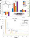
. 2021 Feb 9;33(3):818-833.
doi: 10.1021/acs.chemmater.0c03218. Epub 2021 Jan 21.

Synthesis and Structure-Property Relationships of Polyimide Covalent Organic Frameworks for Carbon Dioxide Capture and (Aqueous) Sodium-Ion Batteries

Affiliations

Synthesis and Structure-Property Relationships of Polyimide Covalent Organic Frameworks for Carbon Dioxide Capture and (Aqueous) Sodium-Ion Batteries

Remco van der Jagt et al. Chem Mater. .

Abstract

Covalent organic frameworks (COFs) are an emerging material family having several potential applications. Their porous framework and redox-active centers enable gas/ion adsorption, allowing them to function as safe, cheap, and tunable electrode materials in next-generation batteries, as well as CO2 adsorption materials for carbon-capture applications. Herein, we develop four polyimide COFs by combining aromatic triamines with aromatic dianhydrides and provide detailed structural and electrochemical characterization. Through density functional theory (DFT) calculations and powder X-ray diffraction, we achieve a detailed structural characterization, where DFT calculations reveal that the imide bonds prefer to form at an angle with one another, breaking the 2D symmetry, which shrinks the pore width and elongates the pore walls. The eclipsed perpendicular stacking is preferable, while sliding of the COF sheets is energetically accessible in a relatively flat energy landscape with a few metastable regions. We investigate the potential use of these COFs in CO2 adsorption and electrochemical applications. The adsorption and electrochemical properties are related to the structural and chemical characteristics of each COF, giving new insights for advanced material designs. For CO2 adsorption specifically, the two best performing COFs originated from the same triamine building block, which-in combination with force-field calculations-revealed unexpected structure-property relationships. Specific geometries provide a useful framework for Na-ion intercalation with retainable capacities and stable cycle life at a relatively high working potential (>1.5 V vs Na/Na+). Although this capacity is low compared to conventional inorganic Li-ion materials, we show as a proof of principle that these COFs are especially promising for sustainable, safe, and stable Na-aqueous batteries due to the combination of their working potentials and their insoluble nature in water.


Conflict of interest statement

The authors declare no competing financial interest.

Figures
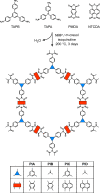
Figure 1
Figure 1
Synthesis scheme and the tags of the four polyimide COFs prepared from TAPB, TAPA, PMDA, and NTCDA.
Figure 2
Figure 2
Energy gain as a function of the torsion angle between the benzene rings of the linkage molecules. All calculations per COF, initialized with an initial torsion of 10, 20, 30, 40, and 50°, relaxed toward the same configuration.
Figure 3
Figure 3
(a) Comparison between the flat and tilted COF configurations. The absolute values of the obtained c-lattice parameters are also provided (green scatter plot, right axis). (b) Effect of the presence of torsion in the crystal lattice of PIB on the PXRD simulated reflections, in comparison with the experimental pattern. Pawley refinement with the flat symmetry resulted in poorer agreement factors consistent with the torsion predicted by the DFT simulations.
Figure 4
Figure 4
(a) Energy difference between the AA eclipsed, AB staggered stacking for the 4 COFs, an illustration of the AA eclipsed, AB staggered and an example of serrated stacking (SE), (b) energy landscape of PID, (c) energy landscape of PIA, and (d) zoom-in in the energy landscape of PID along the direction toward the AB stacking where the metastable SE at an offset of 6.6 Å is visible. Note that the orientation of the unit cell illustration in (a) is not the same as the orientation of the energy maps. In the energy maps, the corners of the hexagons represent the AB staggered configuration.
Figure 5
Figure 5
Experimental (blue line) vs Pawley refined (red scatter) vs simulated (dark green line for AA and light green line for the AB stacking) PXRD data for the (a) PIA, (b) PIB, (c) PIC, and (d) PID COFs.
Figure 6
Figure 6
(a) Carbon dioxide adsorption isotherms of PIA, PIB, PIC, and PID measured at 273 K. (b) Surface areas of PIA, PIB, PIC, and PID measured by nitrogen gas adsorption vs their CO2 capacities measured by CO2 gas adsorption. (c) Force-field simulation of CO2 adsorption at 273 K and 1 bar for the four COFs. The figure combines the adsorbed CO2 density distribution and the potential energy surface, where darker blue areas indicate stronger binding compared to the gray ones.
Figure 7
Figure 7
Plot of low-pressure CO2 uptake against pore diameter for the selected COFs at 273 K and 1 bar. Figure adapted from Zeng et al.(57) with the addition of the results presented here. Adapted with permission from ref (57). Copyright 2016, Wiley-VCH.
Figure 8
Figure 8
(a) Li and (b) Na insertion in PID via DFT calculations; the dark blue areas indicate the most favorable adsorption sites for Li and Na, respectively, and are set as the 0 point reference (scale in eV). (c) Preferable configurational geometry of the intercalated Li and Na. (d) 2-step electron transfer mechanism for the lithiation and sodiation of the COFs.
Figure 9
Figure 9
(a) CV curves at a scan rate of 0.1 mV s–1. (b) Charge–discharge profiles and (c) cycling performance at a rate of 0.1 C (15 mA g–1) for PID in SIB.
Figure 10
Figure 10
Electrochemical performances of PID in the Na0.44MnO2/PID aqueous sodium-ion battery. (a) CV with a scan rate of 0.1 mV s–1. (b) Charge–discharge profiles of cycle 1, 2, 5, 10, and 20 at a C-rate of 0.1 C (15 mA g–1). (c) Cycling performance at a rate of 0.1 C (16 mA g–1).
Figure 11
Figure 11
Review of the presented COF material and reported COFs, CON and MOF materials (2–8). The dotted blue line reflects the thermodynamic HER potential as a function of pH. The vertical length of the boxes reflect their tested operational voltage range and the bold line within the boxes correspond to the voltage where half of the reported capacity is reached. The numbering of the boxes refers to the numbers listed in Table 2.

References

    1. Schon T. B.; McAllister B. T.; Li P.-F.; Seferos D. S. The rise of organic electrode materials for energy storage. Chem. Soc. Rev. 2016, 45, 6405–6406. 10.1039/c6cs90070d. - DOI - PubMed
    1. Aricò A. S.; Bruce P.; Scrosati B.; Tarascon J.-M.; Van Schalkwijk W. Nanostructured materials for advanced energy conversion and storage devices. Nat. Mater. 2005, 4, 366–377. 10.1038/nmat1368. - DOI - PubMed
    1. Liang Y.; Tao Z.; Chen J. Organic electrode materials for rechargeable lithium batteries. Adv. Energy Mater. 2012, 2, 742–769. 10.1002/aenm.201100795. - DOI
    1. Song Z.; Zhou H. Towards sustainable and versatile energy storage devices: an overview of organic electrode materials. Energy Environ. Sci. 2013, 6, 2280–2301. 10.1039/c3ee40709h. - DOI
    1. Morita Y.; Nishida S.; Murata T.; Moriguchi M.; Ueda A.; Satoh M.; Arifuku K.; Sato K.; Takui T. Organic tailored batteries materials using stable open-shell molecules with degenerate frontier orbitals. Nat. Mater. 2011, 10, 947–951. 10.1038/nmat3142. - DOI - PubMed

LinkOut - more resources