. 2021 Feb 2:7:630245.
doi: 10.3389/frobt.2020.630245. eCollection 2020.

How to Model Tendon-Driven Continuum Robots and Benchmark Modelling Performance

Affiliations

How to Model Tendon-Driven Continuum Robots and Benchmark Modelling Performance

Priyanka Rao et al. Front Robot AI. .

Abstract

Tendon actuation is one of the most prominent actuation principles for continuum robots. To date, a wide variety of modelling approaches has been derived to describe the deformations of tendon-driven continuum robots. Motivated by the need for a comprehensive overview of existing methodologies, this work summarizes and outlines state-of-the-art modelling approaches. In particular, the most relevant models are classified based on backbone representations and kinematic as well as static assumptions. Numerical case studies are conducted to compare the performance of representative modelling approaches from the current state-of-the-art, considering varying robot parameters and scenarios. The approaches show different performances in terms of accuracy and computation time. Guidelines for the selection of the most suitable approach for given designs of tendon-driven continuum robots and applications are deduced from these results.

Keywords: modelling; soft arm; soft manipulator; soft robot; tendon actuation.


Conflict of interest statement

The authors declare that the research was conducted in the absence of any commercial or financial relationships that could be construed as a potential conflict of interest.

Figures
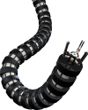
FIGURE 1
FIGURE 1
Example rendering of a tendon-driven continuum robot.
FIGURE 2
FIGURE 2
The modelling framework of a TDCR that considers the tendon actuation to calculate the resulting configuration space parameters. The configuration space parameters can then be used to obtain the corresponding backbone shape in 3D space.
FIGURE 3
FIGURE 3
Schematics of the two typical TDCR design structures: (A) A primary flexible, slender backbone (1) is employed, while equally distributed spacer disks (3) are used to route tendons along the backbone (2); (B) A larger diameter flexible backbone (1) is used that already features inner lumens to guide the tendons (2) without the need of additional spacer disks.
FIGURE 4
FIGURE 4
(A) Diagrammatic representation of one segment of a TDCR, actuated by tension Tk or tendon displacements Δtk on the kth tendon. Dashed line indicates the backbone centreline while the blue solid lines denote the tendons (B) The kth tendon passes through the jth cross section at Pj,k. The tendons are labelled in an anticlockwise manner, arranged radially around the center of the cross section, Oj.
FIGURE 5
FIGURE 5
Diagrammatic representation of various kinematic frameworks used to describe the backbone. The backbone parameters required are denoted by X(s) for distributed backbone parameterization and Xμ for lumped backbone parameterization. (A) Variable curvature representation use to describe the position p(s) using an attached frame, whose orientation is represented by R(s) (B) Arc parameters (κ,ϕ) used to describe a segment with constant curvature without torsion (C) Pseudo-rigid body 3 R model approximating the backbone as a four link serial manipulator (D) Representing the backbone parameters using shape functions ψ(a1,a2,..s) and η(b1,b2..s) in the modal approach.
FIGURE 6
FIGURE 6
Representation of uniformly distributed force fk(s) and tendon termination force Fk exerted on the backbone, by assuming that tendon k follows a continuous path.
FIGURE 7
FIGURE 7
Diagrammatic representation of the forces Fk,j applied by a discrete tendon path, where the portion between two disks is a line segment.
FIGURE 8
FIGURE 8
Proposed classification of different modelling approaches based on the backbone parameters required to define the backbone and assumed tendon path. The left column shows pure kinematic modelling, which maps the tendon lengths to the backbone pose while the statics modelling in the right column considers the backbone properties such as Young’s modulus (E), moment of inertia (I), shear modulus (G) as well as the effect of resulting tendon forces (f(s) or Fj) acting on it.
FIGURE 9
FIGURE 9
Subset of the TDCR configurations considered in the model comparison, for n = 5 and without external forces at the tip. Left: 3D view, Right: Planar view. Maximum or zero tendon tension is applied to each tendon for the two segments. [T1,T2,T3,T4]= 1:[0,0,0,0], 2: [TM,0,TM,0], 3: [0,TM,0,TM], 4: [0,0,TM,0], 5: [0,TM,0,0]. The backbone is represented in black, the spacer disks in blue and the tendons in red.
FIGURE 10
FIGURE 10
Evolution of the models accuracy according to the number of disks per segment. The metrics ep and eR represent the deviation of the tip position and orientation respectively.
FIGURE 11
FIGURE 11
Evolution of the models accuracy according to the backbone stiffness when considering a planar (A–C) and transverse (D–F) tip force for n = 10. The metrics ep and eR represent the deviation of the tip position and orientation respectively.
FIGURE 12
FIGURE 12
Advantages (+) and limitations (−) of each model considered in the case study, in terms of accuracy (blue) and computation time (red), according to the design parameters of a TDCR composed of spacer disks. Forces and limitations for TDCR using lumen to guide the tendons can be obtained by considering the same table but reversing the accuracy ”+” and ”−” signs of the column n < 5. NA: Not applicable.

References

    1. Allen T. F., Rupert L., Duggan T. R., Hein G., Albert K. (2020). “Closed-Form Non-Singular Constant-Curvature Continuum Manipulator Kinematics,” in 3rd IEEE International Conference on Soft Robotics (RoboSoft), New Haven, CT, May 15–July 15, 2020 10.1109/RoboSoft48309.2020.9116015 - DOI
    1. Altenbach H., Bîrsan M., Eremeyev V. A. (2013). “Cosserat-type rods,” in Generalized Continua from the Theory to Engineering Applications, New York: Springer Vienna, 179–248.
    1. Amanov E., Nguyen T.-D., Burgner-Kahrs J. (2019). Tendon-driven continuum robots with extensible sections—a model-based evaluation of path-following motions. Int. J. Robot Res . 10.1177/0278364919886047 - DOI
    1. Ashwin K. P., Ghosal A. (2021). “Forward kinematics of cable-driven continuum robot using optimization method,” in Mechanism and Machine Science, New York: Springer, 391–403. 10.1007/978-981-15-4477-4_27 - DOI
    1. Ashwin K. P., Ghosal A. (2019). “Profile estimation of a cable-driven continuum robot with general cable routing,” in Mechanisms and Machine Science, New York: Springer, 73 1879–1888.

LinkOut - more resources