Review
. 2021 Mar 17;31(12):2008279.
doi: 10.1002/adfm.202008279. Epub 2020 Dec 27.

DNA Transformations for Diagnosis and Therapy

Affiliations
Review

DNA Transformations for Diagnosis and Therapy

So Yeon Ahn et al. Adv Funct Mater. .

Abstract

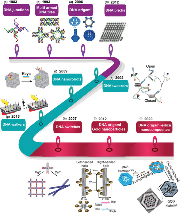
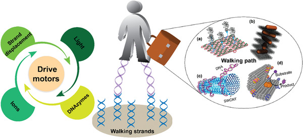
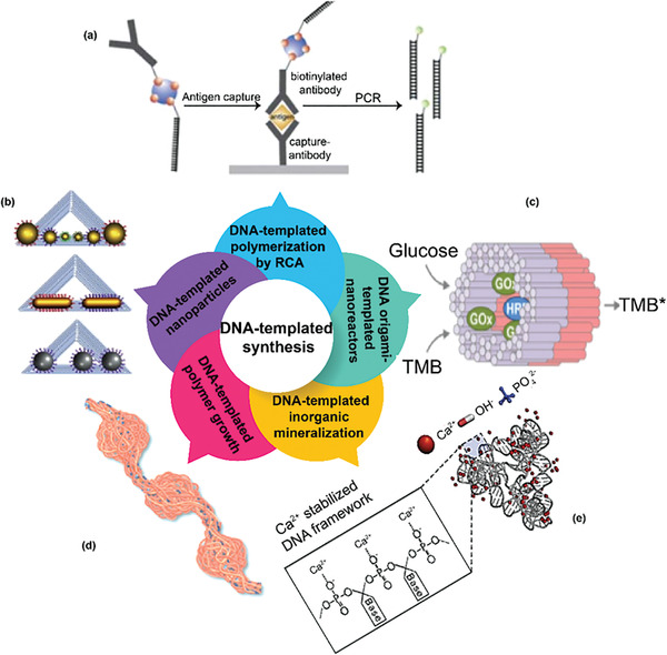
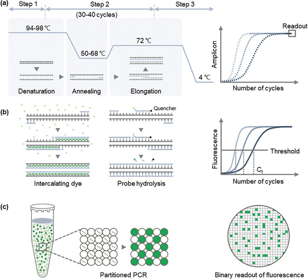
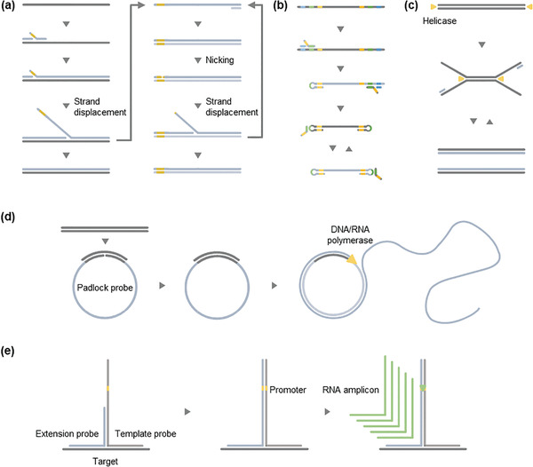
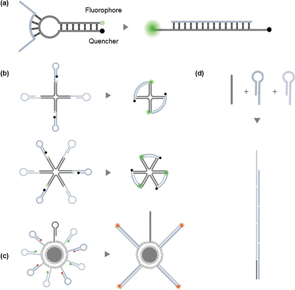
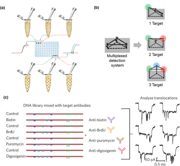
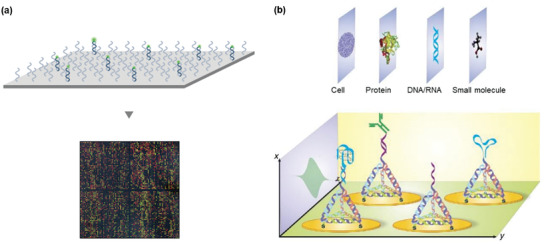
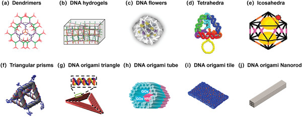
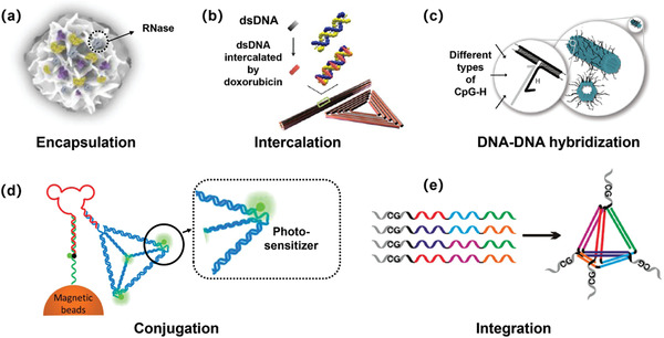
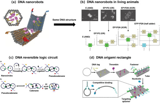
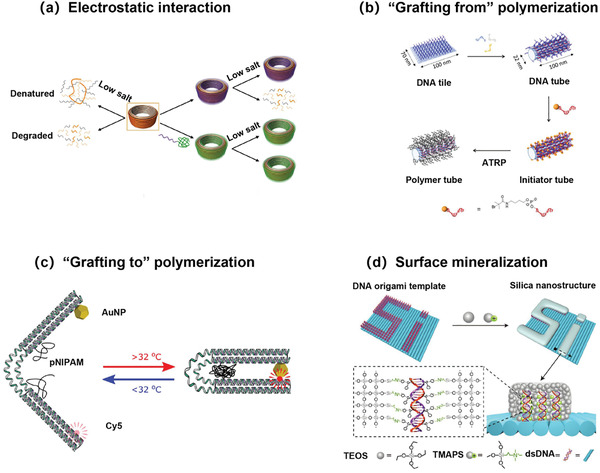
Due to its unique physical and chemical characteristics, DNA, which is known only as genetic information, has been identified and utilized as a new material at an astonishing rate. The role of DNA has increased dramatically with the advent of various DNA derivatives such as DNA-RNA, DNA-metal hybrids, and PNA, which can be organized into 2D or 3D structures by exploiting their complementary recognition. Due to its intrinsic biocompatibility, self-assembly, tunable immunogenicity, structural programmability, long stability, and electron-rich nature, DNA has generated major interest in electronic and catalytic applications. Based on its advantages, DNA and its derivatives are utilized in several fields where the traditional methodologies are ineffective. Here, the present challenges and opportunities of DNA transformations are demonstrated, especially in biomedical applications that include diagnosis and therapy. Natural DNAs previously utilized and transformed into patterns are not found in nature due to lack of multiplexing, resulting in low sensitivity and high error frequency in multi-targeted therapeutics. More recently, new platforms have advanced the diagnostic ability and therapeutic efficacy of DNA in biomedicine. There is confidence that DNA will play a strong role in next-generation clinical technology and can be used in multifaceted applications.

Keywords: DNA transformation; nanomedicine; sensing; theragnostics.


Conflict of interest statement

The authors declare no conflict of interest.

Figures

Figure 1
Figure 1
DNA nanotechnology timeline describing the milestones in static, dynamic, and hybrid DNA nanostructures. a–d) Structural foundations of static DNA nanotechnology and their representative examples mentioned in purple. a) Immobile Holliday junctions by Seeman. Reproduced with permission.[ 2 ] Copyright 2012, Multidisciplinary Digital Publishing Institute. b) 2D and 3D lattices originated from these Holliday junctions. Reproduced with permission.[ 16 ] Copyright 2017, American Chemical Society. c) A seminal approach by Rothemund in 2006 created discrete DNA nanostructures using M13mp18 genome circular single‐strand DNA strand as a scaffold along with the short staple strands, coined as DNA origami. Reproduced with permission.[ 17c ] Copyright 2014, American Chemical Society. d) Finite‐sized, discrete DNA nanostructures called DNA bricks generated via 3D canvas were developed where no intrinsic scaffold is required. Reproduced with permission.[ 17g ] Copyright 2014, Elsevier. e–g) Significant milestones in dynamic DNA nanotechnology which aided DNA locomotion are mentioned in blue. e) The first hybridization energy‐driven DNA nanomachines resembling a pair of tweezers. Reproduced with permission.[ 20a ] Copyright 2000, Springer Nature. f) Controlled opening and closing of the lid using DNA strands with toeholds. Reproduced with permission.[ 17e ] Copyright 2009, Springer Nature. g) Artificial molecular walker capable of reporting its own walking direction through dynamic coupling. Reproduced with permission.[ 19d ] Copyright 2015, Springer Nature. h–j) Hybrid DNA ensembles that arouse from the structural and dynamic nanostructures are denoted in magenta. h) DNA conformational switching with the use of divalent cations. Reproduced with permission.[ 4b ] Copyright 2007, John Wiley and Sons. i) Chiral geometry of the gold nanoparticle arrays on DNA origami. Reproduced with permission.[ 9c ] Copyright 2012, Springer Nature. j) DNA–silica hybrid materials for silicification with prehydrolyzed TMAPS and TEOS. Reproduced with permission.[ 5b ] Copyright 2018, Springer Nature.
Figure 2
Figure 2
Design principle of a walking DNA engines. Three elements mainly contribute to make a static DNA into a dynamic machine. They are a driving motor, a walking path, and a walking strand. The drive motor breaks the initial equilibrium and facilitates the conversion of initial input energy into a mechanical energy, which makes the walking strand to move along the walking track. Reproduced with permission.[ 35a ] Copyright 2019, Elsevier. The walking tracks can be either a) protein adaptors, or b) helical gold nanorods superstructures with tailored chirality, or c) carbon nanotubes, or d) DNA origami nanovault for controlled enzymatic activity. Reproduced with permission.[ 35b ] Copyright 2019, Royal Society of Chemistry. Reproduced with permission.[ 35c ] Copyright 2015, American Chemical Society. Reproduced with permission.[ 35d ] Copyright 2012, Dove Medical Press. Reproduced with permission.[ 35e ] Copyright 2020, Elsevier.
Figure 3
Figure 3
DNA‐templated synthesis technology for various applications. a) DNA‐templated polymerization by rolling circle amplification (RCA). Reproduced with permission.[ 53c ] Copyright 2010, Royal Society of Chemistry. b) DNA‐templated organization of metal nanoparticles. Reproduced with permission.[ 53d ] Copyright 2014, Elsevier. c) DNA‐templated nanoreactors. Reproduced with permission.[ 53 , 119 ] Copyright 2015, Royal Society of Chemistry. d) DNA‐templated polymeric nanowires. Reproduced with permission.[ 53f ] Copyright 2014, American Chemical Society. e) DNA‐templated inorganic mineralization. Reproduced with permission. [ 53g ] Copyright 2020, Elsevier.
Figure 4
Figure 4
Milestones for PCR technologies. a) Schematic of traditional PCR. Steps of PCR consists of denaturation, annealing, and elongation, which are all controlled thermally and are repeated successively by automated thermal cyclers. b) Schematic of real‐time PCR (rtPCR). Amplification of the target sequence is detected by fluorescence real‐time quantitative analysis. In‐depth statistical analysis by measuring the exponential curve obtained during the amplification process. Reproduced with permission.[ 60 ] Copyright 2002, Elsevier. c) Schematic of dPCR. Error‐resistant and refined quantification is achieved through microfluidically partitioned PCR reaction and measurement. Reproduced with permission.[ 61b ] Copyright 2019, Elsevier.
Figure 5
Figure 5
Isothermal amplification methods for sequence‐specific detection. a) Schematics of SDA. The strand synthesized from the extended primer with endonuclease recognition site is displaced by the strand synthesized from the bumper primer. The new cycle of polymerization starts when a nick is formed on the double‐stranded amplicon by endonuclease, with the nicked strand serving as a new primer. Reproduced with permission.[ 64c ] Copyright 2018, Springer Nature. b) Schematics of LAMP. Extension of the primer with a partial complementary sequence to the synthesized strand (yellow region) establishes hybridization and forms a loop structure. The primers then bind to the loop area, where the single‐stranded status is maintained, and polymerization proceeds. The schematics are simplified for clear visualization of loop‐mediated primer binding and elongation. Reproduced with permission.[ 65c ] Copyright 2008, John Wiley and Sons. c) Schematics of HDA. Helicase autonomously unwinds the dsDNA, facilitating binding of the primer and polymerization. Reproduced with permission.[ 68a ] Copyright 2004, John Wiley and Sons. d) Schematics of RCA. The target strand annealed to the padlock probe facilitates circularization of the padlock. The ligated nick on the padlock enables continuous polymerization along the circular template, resulting in a long and repetitive amplicon. Reproduced with permission.[ 72d ] Copyright 2017, Springer Nature. e) Schematics of SMART. As the target, extension probe, and template probe assemble, polymerization along the template probe initiates and results in newly synthesized dsDNA with a promoter sequence for RNA polymerase. RNA polymerase recognizes the double‐stranded promoter and repetitively synthesizes the RNA amplicon. Reproduced with permission.[ 76 ] Copyright 2015, Elsevier.
Figure 6
Figure 6
Entropy‐driven signal amplification methods. a) Schematics of basic molecular beacon. b) Schematics of probes localized on DNA nanostructures for enhanced strand displacement. Reproduced with permission.[ 85 ] Copyright 2019, American Chemical Society. c) Schematics of a DNA nanomachine facilitated by fluidic support. Reproduced with permission.[ 87 ] Copyright 2019, Royal Society of Chemistry. d) Schematics of HCR. Reproduced with permission.[ 90b ] Copyright 2017, Royal Society of Chemistry.
Figure 7
Figure 7
a) Schematics of possible subsampling errors of qPCR. Reproduced with permission.[ 58 ] Copyright 2019, Elsevier. b) Schematics of systemically multiplexed detection based on a DNA prism. Reproduced with permission.[ 97b ] Copyright 2020, Wiley‐VCH. c) Schematics of multiplexing based on barcodes programmed on DNA nanostructures for nanopore analysis. Reproduced with permission.[ 98a ] Copyright 2016, Springer Nature.
Figure 8
Figure 8
High‐throughput surface‐based biosensors. a) Schematics of single‐stranded probe microarray. Reproduced with permission.[ 99b ] Copyright 2000, Future Science. b) Schematics of a surface‐based biosensor with a TDN probe, which is eligible for detection of various biomarkers. Reproduced with permission.[ 102b ] Copyright 2016, Springer Nature.
Figure 9
Figure 9
DNA nanostructures in biomedical applications. a) DNA dendrimer as an efficient nanocarrier of functional nucleic acids for intracellular molecular sensing. Reproduced with permission. [ 123 ] Copyright 2014, American Chemical Society. b) DNA hydrogels. Reproduced with permission.[ 122 ] Copyright 2014, American Chemical Society. c) DNA flowers that allow highly efficient protein loading while retaining the biological activity of the payloads. Reproduced with permission.[ 134 ] Copyright 2017, Wiley‐VCH. d) Tetrahedra displaying antisense motifs able to specifically degrade mRNA and inhibit protein expression in vitro. Reproduced with permission.[ 130 ] Copyright 2011, Wiley‐VCH. e) A synthetic icosahedral DNA‐based host–cargo complex for functional in vivo imaging. Reproduced with permission.[ 133 ] Copyright 2011, Springer Nature. f) Targeted delivery of rab26 siRNA with precisely tailored triangular prisms for lung cancer therapy. Reproduced with permission.[ 128 ] Copyright 2019, Wiley‐VCH. g) DNA origami triangles as an in vivo drug delivery vehicle for cancer therapy. Reproduced with permission.[ 112b ] Copyright 2014, American Chemical Society. h) A modular DNA origami tube‐based enzyme cascade nanoreactor. Reproduced with permission.[ 119 ] Copyright 2015, Royal Society of Chemistry. i) Rectangular DNA origamis coated with virus capsid proteins for efficient cellular delivery. Reproduced with permission.[ 118 ] Copyright 2014, American Chemical Society. j) Daunorubicin‐loaded DNA origami nanorods circumvent drug‐resistance mechanisms in a leukemia model. Reproduced with permission.[ 145 ] Copyright 2015, Wiley‐VCH.
Figure 10
Figure 10
The methods of drug loading for DNA nanostructure. a) One‐Pot synthesis of multiple protein‐encapsulated DNA flowers and their application in intracellular protein delivery. Reproduced with permission.[ 134 ] Copyright 2017, Wiley‐VCH GmbH & Co. KGaA, Weinheim. b) DNA origami as a carrier for circumvention of drug resistance. Reproduced with permission.[ 132 ] Copyright 2012, American Chemical Society. c) Cellular immunostimulation by CpG‐sequence‐coated DNA origami structures. Reproduced with permission.[ 126 ] Copyright 2011, American Chemical Society. d) “Sense‐and‐Treat” DNA nanodevice for synergetic destruction of circulating tumor cells. Reproduced with permission.[ 127 ] Copyright 2016, American Chemical Society. e) Self‐assembled multivalent DNA nanostructures for noninvasive intracellular delivery of immunostimulatory CpG oligonucleotides. Reproduced with permission.[ 55a ] Copyright 2011, American Chemical Society.
Figure 11
Figure 11
a) Schematic of a smart logic‐gated DNA origami nanorobot to target cells and subsequently display the molecular payload. Reproduced with permission.[ 120 ] Copyright 2012, The American Association for the Advancement of Science. b) Schematic of universal computing by DNA origami robots in a living animal. Reproduced with permission.[ 147 ] Copyright 2014, Springer Nature. c) Schematic of interlocked DNA nanostructures controlled by a reversible logic circuit. Reproduced with permission.[ 149 ] Copyright 2014, Springer Nature. d) Schematic of targeting nucleolin to obstruct vasculature feeding with an intelligent DNA nanorobot. Reproduced with permission.[[qv: 141a]] Copyright 2018, Wiley‐VCH.
Figure 12
Figure 12
Decoration of DNA nanostructures. a) Schematic of oligolysine‐based coating protects DNA nanostructures from low‐salt denaturation and nuclease degradation. Reproduced with permission.[ 156b ] Copyright 2017, Springer Nature. b) Schematic of polymer tube nanoreactors via DNA‐origami templated synthesis. Reproduced with permission.[ 157 ] Copyright 2018, Royal Society of Chemistry. c) Schematic of thermo‐responsive actuation of a DNA origami flexor. Reproduced with permission.[ 158a ] Copyright 2018, Wiley‐VCH. d) Schematic of site‐specific synthesis of silica nanostructures on DNA origami templates. Reproduced with permission.[ 160 ] Copyright 2020, Wiley‐VCH.
Figure 13
Figure 13
a) Schematic of a controllable aptamer‐based self‐assembled DNA dendrimer for high‐affinity targeting, bioimaging, and drug delivery. Reproduced with permission.[ 139 ] Copyright 2015, Springer Nature. b) Schematic of a dual‐targeting DNA tetrahedron nanocarrier for breast cancer cell imaging and drug delivery. Reproduced with permission.[ 161 ] Copyright 2018, Elsevier.
Figure 14
Figure 14
DNA nanostructures combined with inorganic nanoparticles. a) Schematic of a self‐assembled DNA origami‐gold nanorod complex for cancer theranostics. Reproduced with permission.[ 112a ] Copyright 2015, Wiley‐VCH. b) Schematic of DNA‐templated silver nanocluster/porphyrin/MnO2 platform for label‐free intracellular Zn2+ imaging and fluorescence/magnetic resonance imaging‐guided photodynamic therapy. Reproduced with permission.[ 163 ] Copyright 2019, American Chemical Society.

Similar articles

Cited by

References

    1. Watson J. D., Crick F. H. C., Nature 1953, 171, 737. - PubMed
    1. Zadegan R. M., Norton M. L., Int. J. Mol. Sci. 2012, 13, 7149. - PMC - PubMed
    1. Li X., Liu D. R., Angew. Chem., Int. Ed. 2004, 43, 4848. - PubMed
    1. a) Shin S. W., Yuk J. S., Chun S. H., Lim Y. T., Um S. H., Nano Convergence 2020, 7, 2; - PMC - PubMed
    2. b) He Y., Tian Y., Chen Y., Ye T., Mao C., Macromol. Biosci. 2007, 7, 1060. - PubMed
    1. a) Zhu J., Wen M., Wen W., Du D., Zhang X., Wang S., Lin Y., Biosens. Bioelectron. 2018, 120, 175; - PubMed
    2. b) Liu X., Zhang F., Jing X., Pan M., Liu P., Li W., Zhu B., Li J., Chen H., Wang L., Lin J., Liu Y., Zhao D., Yan H., Fan C., Nature 2018, 559, 593. - PubMed

LinkOut - more resources