. 2021 Feb 3:15:618626.
doi: 10.3389/fnhum.2021.618626. eCollection 2021.

An Intracortical Implantable Brain-Computer Interface for Telemetric Real-Time Recording and Manipulation of Neuronal Circuits for Closed-Loop Intervention

Affiliations

An Intracortical Implantable Brain-Computer Interface for Telemetric Real-Time Recording and Manipulation of Neuronal Circuits for Closed-Loop Intervention

Hamed Zaer et al. Front Hum Neurosci. .

Abstract

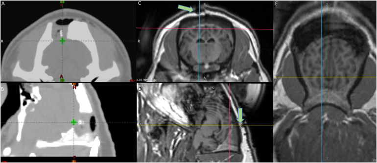
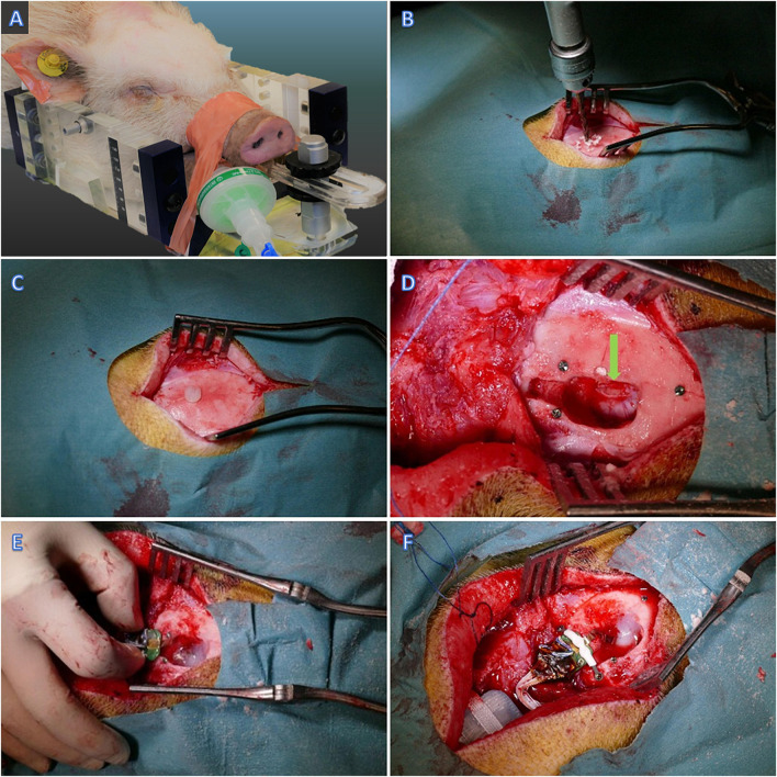
Recording and manipulating neuronal ensemble activity is a key requirement in advanced neuromodulatory and behavior studies. Devices capable of both recording and manipulating neuronal activity brain-computer interfaces (BCIs) should ideally operate un-tethered and allow chronic longitudinal manipulations in the freely moving animal. In this study, we designed a new intracortical BCI feasible of telemetric recording and stimulating local gray and white matter of visual neural circuit after irradiation exposure. To increase the translational reliance, we put forward a Göttingen minipig model. The animal was stereotactically irradiated at the level of the visual cortex upon defining the target by a fused cerebral MRI and CT scan. A fully implantable neural telemetry system consisting of a 64 channel intracortical multielectrode array, a telemetry capsule, and an inductive rechargeable battery was then implanted into the visual cortex to record and manipulate local field potentials, and multi-unit activity. We achieved a 3-month stability of the functionality of the un-tethered BCI in terms of telemetric radio-communication, inductive battery charging, and device biocompatibility for 3 months. Finally, we could reliably record the local signature of sub- and suprathreshold neuronal activity in the visual cortex with high bandwidth without complications. The ability to wireless induction charging combined with the entirely implantable design, the rather high recording bandwidth, and the ability to record and stimulate simultaneously put forward a wireless BCI capable of long-term un-tethered real-time communication for causal preclinical circuit-based closed-loop interventions.

Keywords: EEG; Göttingen minipig; animal model; brain-machine (computer) interface; closed-loop; electrophysiology; neuromodulation; stereotactic radiosurgery.


Conflict of interest statement

MBS and JRA are employees of Zap Surgical Systems, Inc., that funded this study, own stock, and have patents in the field of stereotactic radiosurgery without affecting the trial’s outcome. AD, QF, VG, and JM were employees of Triangle BioSystems International as a division of Harvard Bioscience Inc., however, did not have any influence on the result of the experiments. The remaining authors declare that the research was conducted in the absence of any commercial or financial relationships that could be construed as a potential conflict of interest.

Figures

FIGURE 1
FIGURE 1
Target definition by the fused MRI/CT (A) axial and (B) sagittal view CT scans of the radiotherapy planning system – The green cross shows the target area on the visual cortex (V1) irradiated with 100 Gy. (C) Axial (D) Sagittal (E) Horizontal view MRI images of the brain – the crosshair shows the target area – Green arrows in (C,D) point at the fiducial marker on top of the irradiated area.
FIGURE 2
FIGURE 2
Implantation surgery. (A) The minipig fixated in the MRI compatible head frame. (B) Drilling the skull posterior to Bregma (C,D) Plastic and titanium fiducial markers. (D) Visual cortex exposure – pointed by green arrow. (E) Insertion of the probe in the visual cortex and fixation with Fibrin Sealant. (F) Fixation of the Omnetics connector to the skull bone.
FIGURE 3
FIGURE 3
Electrophysiology results (A) The probe design. Stimulation sites are circled red. (B) Example VEPs recorded from the superficial four layers of electrodes in response to LED flashlight. (C) Example evoked responses stimulated by 100 μA current conducted at electrode 58 (shank 8).
FIGURE 4
FIGURE 4
Schematic view of the probe, target area, and schematic description of the communication loop between the PC and the fully implantable wireless BCI device. (A) Schematic view of the probe with corresponding parts for gray and white matter. (B) Magnified view of the targeted area (V1). (C) Histological coronal view of the brain at the level of the visual cortex. (D) Implantable combo 16 channel stimulation and 48 channel recording capsule interfaced with 64 electrodes cortical array. (F) System overview consisting of RF communication via dongle and receiver to trans-receive commands as well as neural data enabled by independent recording and stimulation software, respectively, along with the implantable capsule with the electrode array. (E) Functional diagram highlighting the information flow through various components of the system for stimulation. (G) Functional diagram for wireless recording system. The red dots are the whole box from preamplifier to multiplexer ADC, which is the custom ASIC. (H) Drawing of near-field induction charging pad worn as a neck belt around the pig. (I) Radio-communication loss for phantom gelatin 2 cm thick to simulate animal tissue with a loss of 4% and (J) Radio loss of 7% in air.
FIGURE 5
FIGURE 5
Benchmark results of temperature and radio-communication. (A) Core implant temperature profile during wireless charging and full operational use (recording and stimulation). Temperature sensor is located with the electronics inside the capsule. The temperature observed on the shell of the implant capsule is 10 C lower than the core temperature. (B) Battery benchmark 3 months post-implantation.
FIGURE 6
FIGURE 6
Histology results showing the necrosis and electrode tract with different stainings. The arrows show necrosis and * – electrode tract (A) Nissl Staining, black pointer: Edema and necrotic changes, approximate cortex diameter 1.95 mm, (B) Isolectin staining (microglia/macrophages), (C) Anti-MBP myelin staining pointer: necrotic area, (D) Anti-GFAP staining, Tissue with enhanced glia response (Scale bar 2 mm).

Similar articles

Cited by

References

    1. Angeles P., Mace M., Admiraal M., Burdet E., Pavese N., Vaidyanathan R. (2016). A Wearable Automated System to Quantify Parkinsonian Symptoms Enabling Closed Loop Deep Brain Stimulation. New York, NY: Springer International Publishing, 8–19.
    1. Arnoux I., Willam M., Griesche N., Krummeich J., Watari H., Offermann N., et al. (2018). Metformin reverses early cortical network dysfunction and behavior changes in Huntington’s disease. Elife 7:38744. 10.7554/eLife.38744 - DOI - PMC - PubMed
    1. Bagheri A., Gabran S. R. I., Salam M. T., Perez Velazquez J. L., Mansour R. R., Salama M. M. A., et al. (2013). Massively-parallel neuromonitoring and neurostimulation rodent headset with nanotextured flexible microelectrodes. IEEE Trans. Biomed. Circuits Syst. 7 601–609. 10.1109/tbcas.2013.2281772 - DOI - PubMed
    1. Ball T., Kern M., Mutschler I., Aertsen A., Schulze-Bonhage A. (2009). Signal quality of simultaneously recorded invasive and non-invasive EEG. Neuroimage 46 708–716. 10.1016/j.neuroimage.2009.02.028 - DOI - PubMed
    1. Bang J. W., Choi J. S., Park K. R. (2013). Noise reduction in brainwaves by using both EEG signals and frontal viewing camera images. Sensors 13 6272–6294. 10.3390/s130506272 - DOI - PMC - PubMed

LinkOut - more resources