. 2021 Jun;34(6):e4499.
doi: 10.1002/nbm.4499. Epub 2021 Feb 22.

A plug-and-play, lightweight, single-axis gradient insert design for increasing spatiotemporal resolution in echo planar imaging-based brain imaging

Affiliations

A plug-and-play, lightweight, single-axis gradient insert design for increasing spatiotemporal resolution in echo planar imaging-based brain imaging

Edwin Versteeg et al. NMR Biomed. 2021 Jun.

Abstract

The goal of this study was to introduce and evaluate the performance of a lightweight, high-performance, single-axis (z-axis) gradient insert design primarily intended for high-resolution functional magnetic resonance imaging, and aimed at providing both ease of use and a boost in spatiotemporal resolution. The optimal winding positions of the coil were obtained using a genetic algorithm with a cost function that balanced gradient performance (minimum 0.30 mT/m/A) and field linearity (≥16 cm linear region). These parameters were verified using field distribution measurements by B0 -mapping. The correction of geometrical distortions was performed using theoretical field distribution of the coil. Simulations and measurements were performed to investigate the echo planar imaging echo-spacing reduction due to the improved gradient performance. The resulting coil featured a 16-cm linear region, a weight of 45 kg, an installation time of 15 min, and a maximum gradient strength and slew rate of 200 mT/m and 1300 T/m/s, respectively, when paired with a commercially available gradient amplifier (940 V/630 A). The field distribution measurements matched the theoretically expected field. By utilizing the theoretical field distribution, geometrical distortions were corrected to within 6% of the whole-body gradient reference image in the target region. Compared with a whole-body gradient set, a maximum reduction in echo-spacing of a factor of 2.3 was found, translating to a 344 μs echo-spacing, for a field of view of 192 mm, a receiver bandwidth of 920 kHz and a gradient amplitude of 112 mT/m. We present a lightweight, single-axis gradient insert design that can provide high gradient performance and an increase in spatiotemporal resolution with correctable geometrical distortions while also offering a short installation time of less than 15 min and minimal system modifications.

Keywords: EPI, gradient coil, insert, magnetic resonance imaging, plug-and-play.


Figures

FIGURE 1
FIGURE 1
(A) The coil design with cooling conduits in red and blue and conductors in brown. The constructed coil (B) with the integrated birdcage transmit coil; (C) on the patient table showing the inside of the 32‐channe l receive array; and (D) schematic drawing of the gradient insert dimensions
FIGURE 2
FIGURE 2
Results of the peripheral nerve stimulation (PNS) measurements for the six volunteers experiencing very mild (A) and clear sensation of PNS (B). Here, each measured combination of gradient strength and rise time is indicate by the dots. The star‐shaped markers indicate combinations of gradient strengths and rise time that resulted in noticeable PNS for one volunteer. The number of star‐shaped markers indicate the number volunteers experiencing noticeable PNS. The numbers in the green boxes indicate the number of volunteers that did not experience any noticeable PNS at a particular rise time
FIGURE 3
FIGURE 3
(A) Simulation results for the maximum field of view (FOV) possible for different combinations of bandwidth and gradient strength. The red line indicates the maximum bandwidth used for the performed experiments in this study; (B) simulation results for the maximum reduction of the echo‐spacing for different combinations of FOV and resolution. The acceleration factor was determined with respect to the maximum performance of our whole‐body gradient set (G = 40 mT/m, SR = 200 T/m/s); (C) the minimum echo spacing achievable using the gradient insert for different combinations of FOV and resolution; (D) the additional reduction factor achievable using three high performance gradient axes (G = 200 mT/m, SR = 1300 T/m/s); and (E) the additional decrease in echo‐spacing achievable when using three high performance gradient axes (G = 200 mT/m, SR = 1300 T/m/s)
FIGURE 4
FIGURE 4
Theoretical and measured field distributions for a driving current of 1 Ampère. (A) Across a line through the gradient insert. (B) In a sagittal slice through the gradient insert. Here, the red sphere indicates the 16‐cm spherical region with ≤5% deviation from linearity. Here, the dashed lines indicate the theoretical field as obtained from the design, and the solid lines show the measured field distribution obtained from the B0‐maps
FIGURE 5
FIGURE 5
Comparison of the geometric distortion produced by (A) the whole‐body z‐gradient before the geometry correction, (B) the whole‐body z‐gradient after the geometry correction, (C) the gradient insert before geometry correction and (D) the gradient insert after geometry correction. Here, the whole‐body system was driven at G = 5 mT/m and  SR = 8 T/m/s and gradient insert at G = 23.5 mT/m and SR = 74 T/m/s
FIGURE 6
FIGURE 6
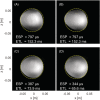
The effect of different combinations of slew rate and gradient strength on the echo‐spacing (ESP) and geometrical distortions apparent in an echo planar imaging (EPI) acquisition (resolution = 1 x 1 mm2; field of view = 192 x 192 mm2) for (A) the whole‐body z‐gradient used at G = 40 mT/m and SR = 200 T/m/s, (B) the gradient insert used at G = 40 mT/m and SR = 200 T/m/s, (C) the gradient insert used at G = 96 mT/m and SR = 800 T/m/s, (D) the gradient insert used at G = 112 mT/m and SR = 1290 T/m/s. Note the decrease in echo‐spacing and geometrical distortion with increased gradient performance. The yellow circle indicates the outline of the physical sphere. ETL, echo train length
FIGURE 7
FIGURE 7
Results of the in vivo example for a single‐shot echo planar imaging (EPI) acquisition of the primary visual cortex (spatial resolution = 1 x 1 mm2; field of view = 192 x 192 mm2) for (A) the whole‐body z‐gradient used at G = 40 mT/m and SR = 200 T/m/s. Note the substantial geometric distortion and signal loss. (B) The gradient insert used at G = 85 mT/m and SR = 616 T/m/s. Note the reduction in distortion observed from the shorter echo train achieved by the gradient insert. (C) The same EPI readout used for a simple visual BOLD functional magnetic resonance imaging (fMRI) experiment: (top) the resulting BOLD activation pattern in the visual cortex; (bottom): the average change in signal in the activated regions during the visual task. ESP, echo‐spacing; ETL, echo train length; ROI, region of interest

References

    1. Mansfield P. Multi‐planar image formation using NMR spin echoes. J Phys C Solid State Phys. 1977;10(3):L55‐L58.
    1. Turner R, Jezzard P, Wen H, et al. Functional mapping of the human visual cortex at 4 and 1.5 tesla using deoxygenation contrast EPI. Magn Reson Med. 1993;29(2):277‐279. - PubMed
    1. Cohen MS, Schmitt F. Echo planar imaging before and after fMRI: A personal history. Neuroimage. 2012;62(2):652‐659. - PMC - PubMed
    1. Wong EC. Local head gradient coils: Window(s) of opportunity. Neuroimage. 2012;62(2):660‐664. - PubMed
    1. Winkler SA, Schmitt F, Landes H, et al. Gradient and shim technologies for ultra high field MRI. Neuroimage. 2018;168:59‐70. - PMC - PubMed

Publication types

LinkOut - more resources