Review
. 2021 Jan 23:2021:3750689.
doi: 10.34133/2021/3750689. eCollection 2021.

Current Research Trends and Perspectives on Solid-State Nanomaterials in Hydrogen Storage

Affiliations
Review

Current Research Trends and Perspectives on Solid-State Nanomaterials in Hydrogen Storage

Jie Zheng et al. Research (Wash D C). .

Abstract

Hydrogen energy, with environment amicable, renewable, efficiency, and cost-effective advantages, is the future mainstream substitution of fossil-based fuel. However, the extremely low volumetric density gives rise to the main challenge in hydrogen storage, and therefore, exploring effective storage techniques is key hurdles that need to be crossed to accomplish the sustainable hydrogen economy. Hydrogen physically or chemically stored into nanomaterials in the solid-state is a desirable prospect for effective large-scale hydrogen storage, which has exhibited great potentials for applications in both reversible onboard storage and regenerable off-board storage applications. Its attractive points include safe, compact, light, reversibility, and efficiently produce sufficient pure hydrogen fuel under the mild condition. This review comprehensively gathers the state-of-art solid-state hydrogen storage technologies using nanostructured materials, involving nanoporous carbon materials, metal-organic frameworks, covalent organic frameworks, porous aromatic frameworks, nanoporous organic polymers, and nanoscale hydrides. It describes significant advances achieved so far, and main barriers need to be surmounted to approach practical applications, as well as offers a perspective for sustainable energy research.


Conflict of interest statement

The authors declare that they have no conflicts of interest.

Figures

Figure 1
Figure 1
Schematic illustration showing the hydrogen storage in nanomaterials and its sustainable applications. Reproducing from ref ([, , –29], and [30]) with permission.
Figure 2
Figure 2
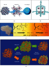
Overview and examples of the solid hydrogen storage systems. (a) Nanoporous carbon materials (carbon nanotube (CNT), (b) MOF, (c) COF, (d) PAFs, (e) the structure of a nanoporous organic polymer (PIM-1) and the composite with a nanoporous filler, and (f) nanohydrides (sodium alanate (NaAlH4)) confined in the nanopores of a MOF (MOF-74) [, –56]. Reproduced with permission [56]. Copyright 2019, American Chemical Society. Reproduced with permission [57]. Copyright 2018, Wiley-VCH. Reproduced with permission [52]. Copyright 2015, American Chemical Society. Reproduced with permission [53]. Copyright 2009, Wiley-VCH. Reproduced with permission [53]. Copyright 2009, Wiley-VCH. Reproduced with permission [55]. Copyright 2013, Materials Research Society and Cambridge University Press.
Figure 3
Figure 3
Hydrogen spillover mechanism in a supported catalyst system: (a) adsorption of hydrogen on a supported metal particle; (b) the low-capacity receptor; (c) primary spillover of atomic hydrogen to the support; (d) secondary spillover to the receptor enhanced by a physical bridge; (e) primary and secondary spillover enhancement by improved contacts and bridges. Reproduced with permission [71]. Copyright 2005, American Chemical Society.
Figure 4
Figure 4
(a) Schematic illustration of the mechanism and formation of metal-organic frameworks (MOFs) [102]. (b) Chemical structure of BDC and MOF-5 and (c) BDC and MOF-177. The structures of MOFs are reproduced with permission [109]. Reproduced with permission [102]. Copyright 2019, Multidisciplinary Digital Publishing Institute. Reproduced with permission [109]. Copyright 2012, American Chemical Society.
Figure 5
Figure 5
Examples of chemical reactions for synthesizing covalent organic frameworks.
Figure 6
Figure 6
Molecular structures of building units (a) and crystal structures of COFs (b–g). Hydrogen atoms are omitted for clarity. Carbon, boron, oxygen, and silicon atoms are represented as gray, orange, red, and blue spheres, respectively. Reproduced with permission [135]. Copyright 2008, American Chemical Society.
Figure 7
Figure 7
(a) Schematic illustration of the synthesis of PAF-1 and Li-doped PAF-1. (b) Computed hydrogen total uptake at 77 K. The inset (b) shows the logarithmic graph of hydrogen total uptake at 77 K. Reproduced with permission [153]. Copyright 2012, Wiley-VCH.
Figure 8
Figure 8
Synthetic routes of (a) hypercrosslinked polymers (HCPs), (b) conjugated microporous polymers (CMPs), and (c) polymers of intrinsic microporosity (PIMs).
Figure 9
Figure 9
(a) Structure of PIM-1, HATN-network-PIM, and CTC-network-PIM. (b) The gravimetric hydrogen adsorption (filled symbols) and desorption (open symbols) at 77 K [181]. Copyright 2006, Wiley-VCH.
Figure 10
Figure 10
(a) Synthesis of triptycene-based porous polymers. (b) Gravimetric hydrogen adsorption and desorption profile isotherms up to 1.13 bar at 77.3 K. Reproduced with permission [184]. Copyright 2012, American Chemical Society.
Figure 11
Figure 11
The preparation of catalyst/nanomaterial composite and hydride/nanomaterial composite.
Figure 12
Figure 12
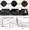
(a) The scheme diagram of the visible-light-driven catalystic procedure over based on the C3N4 with different microstructures. TEM images and the SAED patterns (insets) of (b) Co/C3N4-580 and (c) Ni/C3N4-580 and the elemental maps of Co/C3N4-580 for (d) Co, (e) C, and (f) N and Ni/C3N4-580 for (g) Ni, (h) C, and (i) N. Reproduced with permission [204]. Copyright 2017, American Chemical Society.
Figure 13
Figure 13
(a) TEM image of lattice fringing in MgH2-D occurring from the MgH2hkl = 020 plane. (b) Kinetic hydrogen desorption data for MgH2-D illustrating that equilibrium was reached at different temperatures. Reproduced with permission [216]. Copyright 2010, American Chemical Society.
Figure 14
Figure 14
(a) TEM images of Mg nanocrystals (scale bar = 100 nm). Hydrogen (b) absorption and (c) desorption of the Mg nanocrystals at different temperatures. Reproduced with permission [220]. Copyright 2011, American Chemical Society.
Figure 15
Figure 15
(a) Preparation of the self-assembled MgH2 on three-dimensional (3D) metal interacted carbon. (b) SEM images of metal interacted carbon. (c) SEM and (d) TEM images of the MgH2 embedded hollow 3D architecture of carbon (MHCH). The inset (d) shows the histogram distribution of MHCH size distributions. (e) Hydrogen absorption (at 10 bar) and (f) desorption (at 0.01 bar) of the MHCH at different temperatures. The inset (e) shows the hydrogen absorption of the MHCH at 25°C for 250 h. Reproduced with permission [222]. Copyright 2017, Royal Society of Chemistry.
Figure 16
Figure 16
(a) The schematic representation of AB confined into the Pd/HNTs to generate H2 at 60°C. (b) MS profiles of AB, AB/HNTs, and AB@Pd/HNTs. Reproduced with permission [231]. Copyright 2020, American Chemical Society.
Figure 17
Figure 17
(a) AB@MOF-5 nanocomposite [232]. (b) AB@PAF-1 nanocomposite [235]. (c) PMA-AB polymeric nanocomposite and its proposed thermolysis mechanism [233]. (d) The preparation of AB-PSDB polymeric nanocomposite [234]. (e) Reproduced with permission [232]. Copyright 2014, Royal Society of Chemistry. Reproduced with permission [235]. Copyright 2012, American Chemical Society. Reproduced with permission [233]. Copyright 2010, Wiley-VCH. Reproduced with permission [234]. Copyright 2012, Royal Society of Chemistry.
Figure 18
Figure 18
(a) General schematic of a polymer electrolyte membrane fuel cell. (b) Thermal integration between the hydrogen storage system and the fuel cell.
Figure 19
Figure 19
Schematic diagram of the operation of a CSP system during the (a) daytime and (b) night time.
Figure 20
Figure 20
(a) Fuel cell vehicle with onboard storage. (b) Schematic representation of the hybrid system for a net-zero-energy residential environment. The arrows represent the energy flows between the components [284]. Reproduced with permission [284]. Copyright 2018, Elsevier.

References

    1. Smil V. Energy In World History. Abingdon, UK: Routledge; 2019. - DOI
    1. Rhodes R. Energy:A Human History. New York, USA: Simon and Schuster; 2019.
    1. Letcher T. M. Future Energy: Improved, Sustainable and Clean Options for Our Planet. Amsterdam, Netherlands: Elsevier; 2020.
    1. Poizot P., Gaubicher J., Renault S., Dubois L., Liang Y., Yao Y. Opportunities and Challenges for Organic Electrodes in Electrochemical Energy Storage. Chemical Reviews. 2020;120(14):6490–6557. doi: 10.1021/acs.chemrev.9b00482. - DOI - PubMed
    1. Carrillo A. J., Gonzalez-Aguilar J., Romero M., Coronado J. M. Solar Energy on Demand: A Review on High Temperature Thermochemical Heat Storage Systems and Materials. Chemical Reviews. 2019;119(7):4777–4816. doi: 10.1021/acs.chemrev.8b00315. - DOI - PubMed

LinkOut - more resources