Concept description and accuracy evaluation of a moldable surgical targeting system
- PMID: 33634206
- PMCID: PMC7893323
- DOI: 10.1117/1.JMI.8.1.015003
Concept description and accuracy evaluation of a moldable surgical targeting system
Abstract
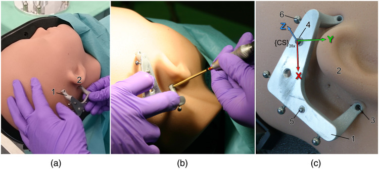
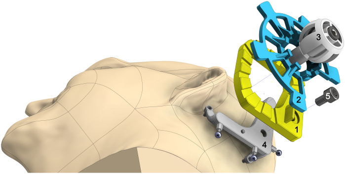
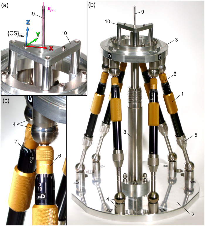
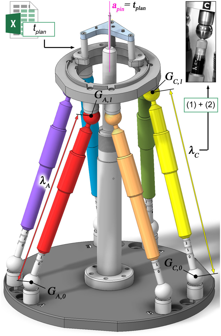
Purpose: We explain our concept for customization of a guidance instrument, present a prototype, and describe a set of experiments to evaluate its positioning and drilling accuracy. Methods: Our concept is characterized by the use of bone cement, which enables fixation of a specific configuration for each individual surgical template. This well-established medical product was selected to ensure future intraoperative fabrication of the template under sterile conditions. For customization, a manually operated alignment device is proposed that temporary defines the planned trajectory until the bone cement is hardened. Experiments ( ) with half-skull phantoms were performed. Analysis of accuracy comprises targeting validations and experiments including drilling in bone substitutes. Results: The resulting mean positioning error was found to be at the level of the target point whereas drilling was possible with a mean accuracy of . Conclusion: We proposed a cost-effective, easy-to-use approach for accurate instrument guidance that enables template fabrication under sterile conditions. The utilization of bone cement was proven to fulfill the demands of an easy, quick, and prospectively intraoperatively doable customization. We could demonstrate sufficient accuracy for many surgical applications, e.g., in neurosurgery. The system in this early development stage already outperforms conventional stereotactic frames and image-guided surgery systems in terms of targeting accuracy.
Keywords: cochlear implantation; image-guided surgery; micro-stereotactic frame; minimally invasive surgery; surgical template.
© 2021 The Authors.
Figures
Similar articles
-
Drilling accuracy evaluation of a mouldable surgical targeting system for minimally invasive access to anatomic targets in the temporal bone.Eur Arch Otorhinolaryngol. 2023 Oct;280(10):4371-4379. doi: 10.1007/s00405-023-07925-x. Epub 2023 Apr 3. Eur Arch Otorhinolaryngol. 2023. PMID: 37010602 Free PMC article.
-
Accuracy of linear drilling in temporal bone using drill press system for minimally invasive cochlear implantation.Int J Comput Assist Radiol Surg. 2016 Mar;11(3):483-93. doi: 10.1007/s11548-015-1261-7. Epub 2015 Jul 17. Int J Comput Assist Radiol Surg. 2016. PMID: 26183149 Free PMC article.
-
Configuration optimization and experimental accuracy evaluation of a bone-attached, parallel robot for skull surgery.Int J Comput Assist Radiol Surg. 2016 Mar;11(3):421-36. doi: 10.1007/s11548-015-1300-4. Epub 2015 Sep 26. Int J Comput Assist Radiol Surg. 2016. PMID: 26410844
-
Workflow and simulation of image-to-physical registration of holes inside spongy bone.Int J Comput Assist Radiol Surg. 2017 Aug;12(8):1425-1437. doi: 10.1007/s11548-017-1594-5. Epub 2017 May 6. Int J Comput Assist Radiol Surg. 2017. PMID: 28478518 Review.
-
Evolution and Stagnation of Image Guidance for Surgery in the Lateral Skull: A Systematic Review 1989-2020.Front Surg. 2021 Jan 11;7:604362. doi: 10.3389/fsurg.2020.604362. eCollection 2020. Front Surg. 2021. PMID: 33505986 Free PMC article.
Cited by
-
Pull-Out Strength of Orthodontic Miniscrews in the Temporal Bone.J Otolaryngol Head Neck Surg. 2024 Jan-Dec;53:19160216241248669. doi: 10.1177/19160216241248669. J Otolaryngol Head Neck Surg. 2024. PMID: 38903014 Free PMC article.
-
Minimally Invasive Cochlear Implantation: First-in-Man of Patient-Specific Positioning Jigs.Front Neurol. 2022 Apr 25;13:829478. doi: 10.3389/fneur.2022.829478. eCollection 2022. Front Neurol. 2022. PMID: 35547379 Free PMC article.
References
LinkOut - more resources
Full Text Sources
Other Literature Sources