. 2021 May 12;21(9):3715-3720.
doi: 10.1021/acs.nanolett.0c04696. Epub 2021 Feb 26.

Neuromorphic Binarized Polariton Networks

Affiliations

Neuromorphic Binarized Polariton Networks

Rafał Mirek et al. Nano Lett. .

Abstract

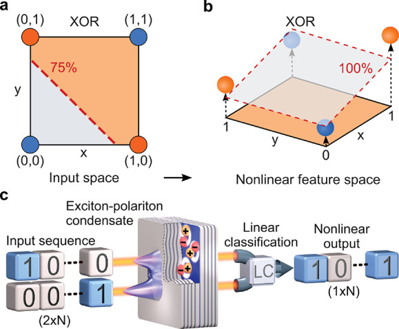
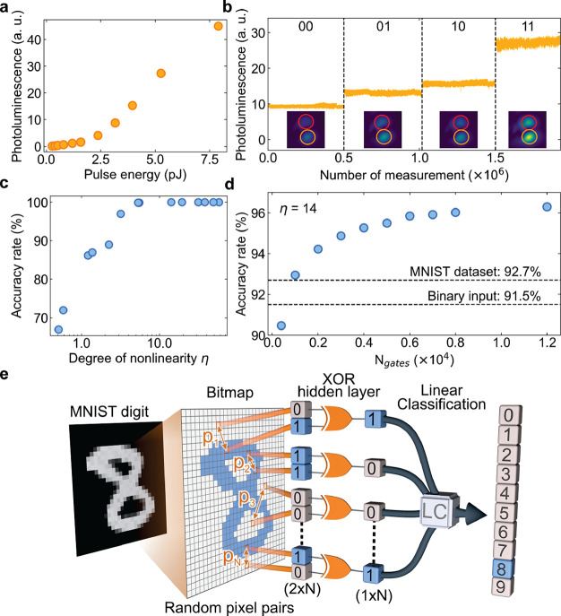
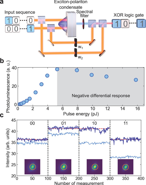
The rapid development of artificial neural networks and applied artificial intelligence has led to many applications. However, current software implementation of neural networks is severely limited in terms of performance and energy efficiency. It is believed that further progress requires the development of neuromorphic systems, in which hardware directly mimics the neuronal network structure of a human brain. Here, we propose theoretically and realize experimentally an optical network of nodes performing binary operations. The nonlinearity required for efficient computation is provided by semiconductor microcavities in the strong quantum light-matter coupling regime, which exhibit exciton-polariton interactions. We demonstrate the system performance against a pattern recognition task, obtaining accuracy on a par with state-of-the-art hardware implementations. Our work opens the way to ultrafast and energy-efficient neuromorphic systems taking advantage of ultrastrong optical nonlinearity of polaritons.

Keywords: binary network; exciton-polaritons; microcavities; nonlinear optics; semiconductors.


Conflict of interest statement

The authors declare no competing financial interest.

Figures

Figure 1
Figure 1
Nonlinear classification and experimental realization. (a) The XOR operation is a generic classification problem that is linearly inseparable in the space of inputs—there exists no straight line separating points corresponding to the “0” and “1” results marked with blue and orange circles, respectively. (b) An additional feature, represented by the z axis, which is a nonlinear function of inputs, allows for performing classification with a two-dimensional plane. (c) Experimental realization in an exciton–polariton system. A series of picosecond pulses encoding the inputs are incident on a semiconductor microcavity in the strong coupling regime, triggering a nonlinear response as a result of bosonic condensation. The emission is used to perform linear classification.
Figure 2
Figure 2
Optoelectronic machine learning. (a) The nonlinear dependence of the total emission intensity from the condensation site on the energy of two input pulses. (b) Emission in the four input configurations demonstrates nonlinearity. Insets show typical real-space emission observed on a CCD camera for each realization. The same color scale is preserved for each panel. Image size is of ∼7 μm × 7 μm. (c) Accuracy of the XOR gate as a function of the useful degree of nonlinearity η. (d) Accuracy of the MNIST handwritten digit prediction versus the number of XOR gates. Dashed lines show the benchmarks of software linear classification for the full and binarized MNIST input. (e) Conceptual scheme of the network with a single hidden layer of XOR gates.
Figure 3
Figure 3
All-optical implementation of XOR gate. (a) Scheme of the experimental setup, in which the linear classification of Figure 1b is implemented with two auxiliary pulse paths controlled with neutral density filters, corresponding to weights w1 and w2. (b) Dependence of emission intensity on the energy of excitation pulses for equal pulse energy in both pulses. The spectral filter placed behind the sample allows for obtaining a negative differential response of the condensate emission. (c) Measured filtered emission intensity for all four combinations of inputs (blue) and the output intensity of the all-optical XOR gate (dark blue), which consists of the emission combined with the weighted inputs. Black dashed lines separate realizations of different inputs. Red dashed lines indicate the gate output intensity levels corresponding to results “0” and “1”. Insets show typical real-space emission observed on a CCD camera for each realization. The same color scale is preserved for each panel. Image size is of ∼6 μm × 6 μm.

References

    1. LeCun Y.; Bengio Y.; Hinton G. Deep learning. Nature 2015, 521, 436–444. 10.1038/nature14539. - DOI - PubMed
    1. Misra J.; Saha I. Artificial neural networks in hardware: A survey of two decades of progress. Neurocomputing 2010, 74, 239–255. 10.1016/j.neucom.2010.03.021. - DOI
    1. Merolla P. A.; et al. A million spiking-neuron integrated circuit with a scalable communication network and interface. Science 2014, 345, 668–673. 10.1126/science.1254642. - DOI - PubMed
    1. Kitayama K.-i.; Notomi M.; Naruse M.; Inoue K.; Kawakami S.; Uchida A. Novel frontier of photonics for data processing-Photonic accelerator. APL Photonics 2019, 4, 090901.10.1063/1.5108912. - DOI
    1. Xu X.; Ding Y.; Hu S. X.; Niemier M.; Cong J.; Hu Y.; Shi Y. Scaling for edge inference of deep neural networks. Nature Electronics 2018, 1, 216–222. 10.1038/s41928-018-0059-3. - DOI

Publication types