Review
. 2021 Mar 1;77(Pt 3):313-324.
doi: 10.1107/S2059798320016368. Epub 2021 Feb 17.

Macromolecular crystallography using microcrystal electron diffraction

Affiliations
Review

Macromolecular crystallography using microcrystal electron diffraction

Max T B Clabbers et al. Acta Crystallogr D Struct Biol. .

Abstract

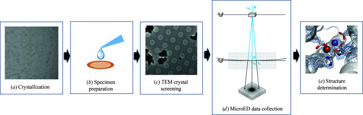
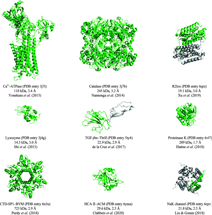
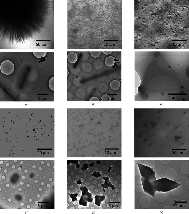
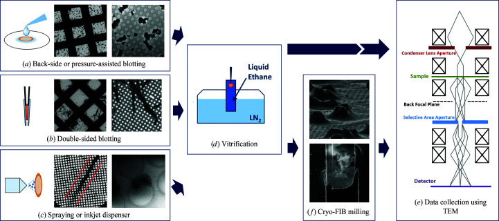
Microcrystal electron diffraction (MicroED) has recently emerged as a promising method for macromolecular structure determination in structural biology. Since the first protein structure was determined in 2013, the method has been evolving rapidly. Several protein structures have been determined and various studies indicate that MicroED is capable of (i) revealing atomic structures with charges, (ii) solving new protein structures by molecular replacement, (iii) visualizing ligand-binding interactions and (iv) determining membrane-protein structures from microcrystals embedded in lipidic mesophases. However, further development and optimization is required to make MicroED experiments more accurate and more accessible to the structural biology community. Here, we provide an overview of the current status of the field, and highlight the ongoing development, to provide an indication of where the field may be going in the coming years. We anticipate that MicroED will become a robust method for macromolecular structure determination, complementing existing methods in structural biology.

Keywords: 3D electron diffraction; electron crystallography; macromolecular crystallography; methods development; microcrystal electron diffraction.


Figures

Figure 1
Figure 1
Schematic overview of a typical workflow involved in MicroED. (a) Microcrystals are grown using sitting-drop vapour diffusion. When a crystallization drop is identified containing potential microcrystals suitable for MicroED, the drop is mixed with buffer solution and (b) deposited on a standard EM grid. Excess liquid is blotted away using filter paper, either from the back-side or both sides of the grid, and the grid is vitrified and cryo-transferred to the TEM. (c) In imaging mode, the grid can be screened for thin hydrated protein microcrystals that are suitable for data collection. (d) Switching to diffraction mode, MicroED data can be collected by continuously rotating the microcrystal about the rotation axis, effectively rotating the crystal lattice in reciprocal space, analogous to the rotation method in macromolecular X-ray crystallography. The diffraction patterns can then be indexed, the intensities are extracted and the structure can be determined by molecular replacement (e) followed by model building and structure refinement.
Figure 2
Figure 2
Highlighting several protein structures determined by MicroED. Figures were prepared using the PyMOL molecular-graphics system version 2.2.3 (Schrödinger).
Figure 3
Figure 3
Typical crystal morphologies suitable for MicroED as seen under an optical microscope (top) and on the grid using TEM (bottom). (a) Needle-shaped nanocrystals of orthorhombic hen egg-white lysozyme; the crystals are 100–200 nm in thickness and several micrometres in length (Clabbers et al., 2017; Xu et al., 2018 ▸). (b) Needle-shaped dynamin GTPase microcrystals of 0.5–1.5 µm in diameter and several micrometres in length. (c) Triangular-shaped plate-like R2lox crystals; the crystals are less than 500 nm in thickness and a few micrometres in size (Xu et al., 2019 ▸). (d) Fragments of large HCA II crystals; the fragments are 1–2 µm in size with a thickness of less than 500 nm (Fisher et al., 2012; Clabbers et al., 2020 ▸). (e) Fragmented crystals of tetragonal lysozyme; individual fragments are around 1 µm in size (Barends et al., 2014 ▸). (f) Diamond-shaped R2c crystals of 2–15 µm in size. As the thinner edges of the crystals did not diffract well, MicroED data had to be collected from smaller crystals (Andersson & Högbom, 2009 ▸).
Figure 4
Figure 4
Schematic overview of the specimen preparation involved in MicroED. The aim of specimen preparation is to rapidly vitrify the hydrated protein crystals, while keeping a thin layer of vitrified ice around the crystals to protect them from the vacuum and electron beam radiation during MicroED data collection (Dubochet et al., 1988; Shi et al., 2016 ▸). (a) The protein crystal suspension is typically deposited on a 3 mm TEM grid (Quantifoil or lacey carbon). Prior to vitrification, any excess liquid can be removed by back-side blotting (Martynowycz & Gonen, 2020 ▸), pressure-assisted blotting (Zhao et al., 2019 ▸) or (b) double-sided blotting (Shi et al., 2016 ▸). (c) Alternatively, a small amount of crystal suspension can be sprayed onto a self-wicking grid, leaving a line of thin liquid trail covering approximately 50 grid squares, as highlighted by the red lines in the figure (Jain et al., 2012; Klebl et al., 2020 ▸). The concentration of the crystals in the suspension needs to be tuned to avoid clogging the nozzle of the inkjet. (d) After the excess liquid has been removed from the grid by any of the methods introduced above (ac), the grid is then rapidly plunged into liquid ethane. (e) If the prepared specimen is of suitable thickness, MicroED data can be collected straight away using TEM. (f) Otherwise, cryo-FIB milling can be used to make thin crystalline lamella of the sample suitable for MicroED data collection (Duyvesteyn et al., 2018; Zhou et al., 2019; Martynowycz et al., 2019a ,b).

Similar articles

Cited by

References

    1. Afonine, P. V., Grosse-Kunstleve, R. W., Echols, N., Headd, J. J., Moriarty, N. W., Mustyakimov, M., Terwilliger, T. C., Urzhumtsev, A., Zwart, P. H. & Adams, P. D. (2012). Acta Cryst. D68, 352–367. - PMC - PubMed
    1. Andersson, C. S. & Högbom, M. (2009). Proc. Natl Acad. Sci. USA, 106, 5633–5638. - PMC - PubMed
    1. Arndt, U. W. & Wonacott, A. J. (1977). The Rotation Method in Crystallography. Amsterdam: North Holland.
    1. Barends, T. R. M., Foucar, L., Botha, S., Doak, R. B., Shoeman, R. L., Nass, K., Koglin, J. E., Williams, G. J., Boutet, S., Messerschmidt, M. & Schlichting, I. (2014). Nature, 505, 244–247. - PubMed
    1. Bartesaghi, A., Merk, A., Banerjee, S., Matthies, D., Wu, X., Milne, J. L. S. & Subramaniam, S. (2015). Science, 348, 1147–1151. - PMC - PubMed

Substances