

Ion-Imprinted Polymers: Synthesis, Characterization, and Adsorption of Radionuclides
- PMID: 33652580
- PMCID: PMC7956459
- DOI: 10.3390/ma14051083
Ion-Imprinted Polymers: Synthesis, Characterization, and Adsorption of Radionuclides
Abstract
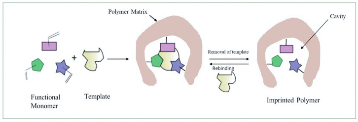
Growing concern over the hazardous effect of radionuclides on the environment is driving research on mitigation and deposition strategies for radioactive waste management. Currently, there are many techniques used for radionuclides separation from the environment such as ion exchange, solvent extraction, chemical precipitation and adsorption. Adsorbents are the leading area of research and many useful materials are being discovered in this category of radionuclide ion separation. The adsorption technologies lack the ability of selective removal of metal ions from solution. This drawback is eliminated by the use of ion-imprinted polymers, these materials having targeted binding sites for specific ions in the media. In this review article, we present recently published literature about the use of ion-imprinted polymers for the adsorption of 10 important hazardous radionuclides-U, Th, Cs, Sr, Ce, Tc, La, Cr, Ni, Co-found in the nuclear fuel cycle.
Keywords: adsorption; ion-imprinted polymers; radioactive waste; radionuclides; separation.
Conflict of interest statement
The authors declare no conflict of interest. The funders had no role in the design of the study; in the collection, analyses, or interpretation of data; in the writing of the manuscript, or in the decision to publish the results.
Figures
References
-
- Keith S., Faroon O., Roney N., Scinicariello F., Wilbur S., Ingerman L., Llados F., Plewak D., Wohlers D., Diamond G. Toxicological Profile for Uranium. Agency for Toxic Substances and Disease Registry; Atlanta, GA, USA: 2013. - PubMed
-
- Horne G.P., Zarzana C.A., Grimes T.S., Rae C., Ceder J., Mezyk S.P., Mincher B.J., Charbonnel M.-C., Guilbaud P., Saint-Louis G. Effect of Chemical Environment on the Radiation Chemistry of N, N-Di-(2-Ethylhexyl) Butyramide (DEHBA) and Plutonium Retention. Dalton Trans. 2019;48:14450–14460. doi: 10.1039/C9DT02383F. - DOI - PubMed
-
- Manaka M., Seki Y., Okuzawa K., Watanabe Y. Uranium Sorption onto Natural Sediments within a Small Stream in Central Japan. Limnology. 2008;9:173–183. doi: 10.1007/s10201-008-0249-1. - DOI
-
- Nordberg G.F., Fowler B.A., Nordberg M., Friberg L. Handbook on the Toxicology of Metals. Academic Press; Amsterdam, The Netherlands: 2007. p. 1024.
Publication types
Grants and funding
LinkOut - more resources
Full Text Sources
Other Literature Sources
Research Materials
