

Non-line-of-sight imaging over 1.43 km
- PMID: 33658383
- PMCID: PMC7958383
- DOI: 10.1073/pnas.2024468118
Non-line-of-sight imaging over 1.43 km
Abstract
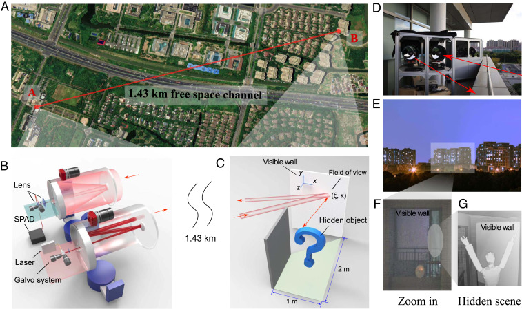
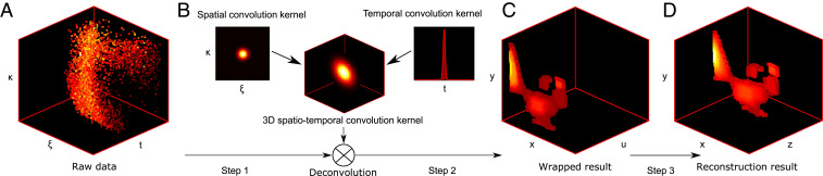
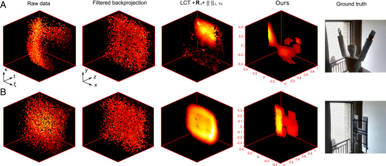
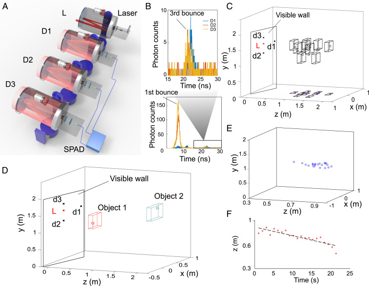
Non-line-of-sight (NLOS) imaging has the ability to reconstruct hidden objects from indirect light paths that scatter multiple times in the surrounding environment, which is of considerable interest in a wide range of applications. Whereas conventional imaging involves direct line-of-sight light transport to recover the visible objects, NLOS imaging aims to reconstruct the hidden objects from the indirect light paths that scatter multiple times, typically using the information encoded in the time-of-flight of scattered photons. Despite recent advances, NLOS imaging has remained at short-range realizations, limited by the heavy loss and the spatial mixing due to the multiple diffuse reflections. Here, both experimental and conceptual innovations yield hardware and software solutions to increase the standoff distance of NLOS imaging from meter to kilometer range, which is about three orders of magnitude longer than previous experiments. In hardware, we develop a high-efficiency, low-noise NLOS imaging system at near-infrared wavelength based on a dual-telescope confocal optical design. In software, we adopt a convex optimizer, equipped with a tailored spatial-temporal kernel expressed using three-dimensional matrix, to mitigate the effect of the spatial-temporal broadening over long standoffs. Together, these enable our demonstration of NLOS imaging and real-time tracking of hidden objects over a distance of 1.43 km. The results will open venues for the development of NLOS imaging techniques and relevant applications to real-world conditions.
Keywords: computational imaging; computer vision; non–line-of-sight imaging; optical imaging.
Copyright © 2021 the Author(s). Published by PNAS.
Conflict of interest statement
The authors declare no competing interest.
Figures
References
-
- Altmann Y., et al. , Quantum-inspired computational imaging. Science 361, eaat2298 (2018). - PubMed
-
- Maeda T., Satat G., Swedish T., Sinha L., Raskar R., Recent advances in imaging around corners. arXiv:1910.05613 (12 October 2019).
-
- Faccio D., Velten A., Wetzstein G., Non-line-of-sight imaging. Nat. Rev. Phys. 2, 318–327 (2020).
-
- Kirmani A., Hutchison T., Davis J., Raskar R., “Looking around the corner using transient imaging” in Proceedings of the 12th IEEE International Conference on Computer Vision. (IEEE, 2009), pp. 159–166.
-
- Velten A., et al. , Recovering three-dimensional shape around a corner using ultrafast time-of-flight imaging. Nat. Commun. 3, 745 (2012). - PubMed
Publication types
LinkOut - more resources
Full Text Sources
Other Literature Sources
