

Experimental validation of new self-voltage balanced 9L-ANPC inverter for photovoltaic applications
- PMID: 33658562
- PMCID: PMC7930242
- DOI: 10.1038/s41598-021-84531-z
Experimental validation of new self-voltage balanced 9L-ANPC inverter for photovoltaic applications
Abstract
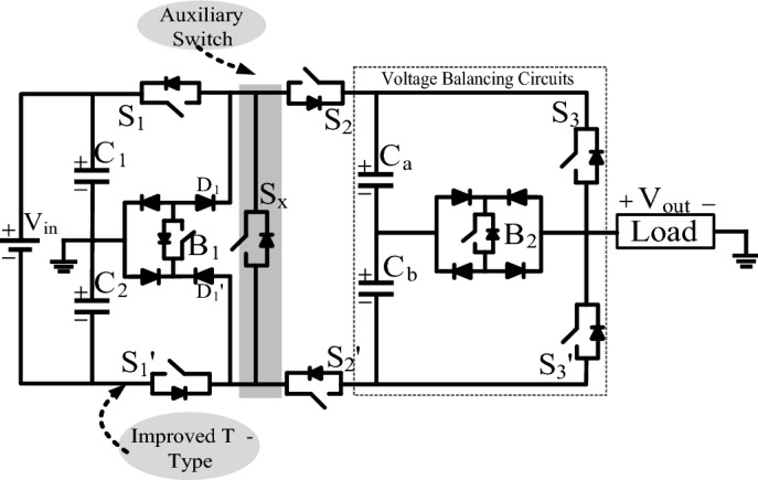
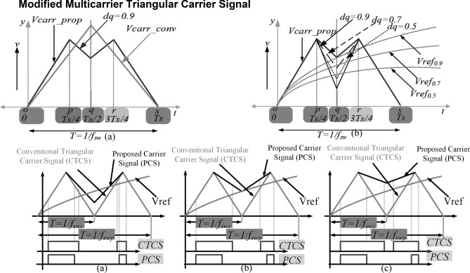
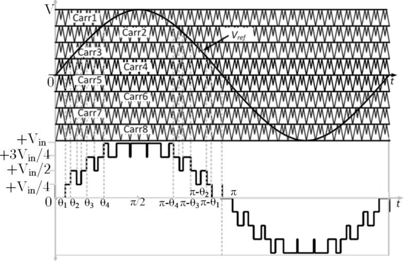
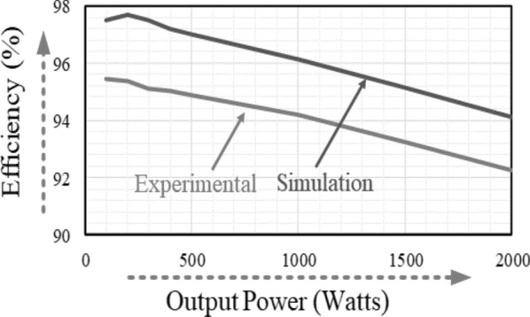
Multilevel inverters play an important role in extracting the power from renewable energy resources and delivering the output voltage with high quality to the load. This paper proposes a new single-stage switched capacitor nine-level inverter, which comprises an improved T-type inverter, auxiliary switch, and switched cell unit. The proposed topology effectively reduces the DC-link capacitor voltage and exhibits superior performance over recently switched-capacitor inverter topologies in terms of the number of power components and blocking voltage of the switches. A level-shifted multilevel pulse width modulation scheme with a modified triangular carrier wave is implemented to produce a high-quality stepped output voltage waveform with low switching frequency. The proposed nine-level inverter's effectiveness, driven by the recommended modulation technique, is experimentally verified under varying load conditions. The power loss and efficiency for the proposed nine-level inverter are thoroughly discussed with different loads.
Conflict of interest statement
The authors declare no competing interests.
Figures

References
-
- Franquelo LG, Rodriguez J, Leon JI, Kouro S, Portillo R, Prats MAM. The age of multilevel converters arrives. IEEE Trans. Ind. Electron. Mag. 2008;2(2):28–39. doi: 10.1109/MIE.2008.923519. - DOI
-
- Sathik MJ, Bhatnagar K, Sandeep N, Blaabjerg F. An improved seven-level PUC inverter topology with voltage boosting. IEEE Trans. Circuits Syst. II Express Brief. 2020;67(1):127–131. doi: 10.1109/TCSII.2019.2902908. - DOI
-
- Jagabar-Sathik M, Vijayakumar K. An assessment of recent multilevel inverter topologies with reduced power electronics components for renewable applications. Renew. Sustain. Energy Rev. 2018;82(3):3379–3399.
Grants and funding
LinkOut - more resources
Full Text Sources
Other Literature Sources
