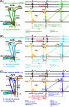
Antegrade slow pathway mapping of typical atrioventricular nodal reentrant tachycardia based on direct slow pathway capture
- PMID: 33664895
- PMCID: PMC7896471
- DOI: 10.1002/joa3.12484
Antegrade slow pathway mapping of typical atrioventricular nodal reentrant tachycardia based on direct slow pathway capture
Abstract
Background: Radiofrequency (RF) ablation of typical atrioventricular nodal reentrant tachycardia (tAVNRT) is performed without revealing out the location of antegrade slow pathway (ASp). In this study, we studied a new electrophysiological method of identifying the site of ASp.
Methods: This study included 19 patients. Repeated series of very high-output single extrastimulations (VhoSESts) were delivered at the anatomical slow pathway region during tAVNRT. Tachycardia cycle length (TCL), coupling interval (CI), and return cycle (RC) were measured and the prematurity of VhoSESts [ΔPM (= TCL - CI)] and the prolongation of RCs [ΔPL (= RC - TCL)] were calculated. Pacing sites were classified into two categories: (i) ASp capture sites [DSPC(+) sites], where two different RCs were shown, and ASp non-capture sites [DSPC(-) sites], where only one RC was shown. RF ablation was performed at DSPC(+) sites and/or sites with catheter-induced mechanical trauma (CIMT) to ASp.
Results: DSPC(+) sites were shown in 13 patients (68%). RF ablation was successful in all patients without any degree of atrioventricular block nor recurrence. Total number of RF applications was 1.8 ± 1.1. Minimal distance between successful ablation sites and DSPC(+)/CIMT sites and His bundle (HB) electrogram recording sites was 1.9 ± 0.8 mm and 19.8 ± 6.1 mm, respectively. ΔPL of more than 92.5 ms, ΔPL/TCL of more than 0.286, and ΔPL/ΔPM of more than 1.565 could identify ASp with sensitivity of 100%, 91.1%, and 88.9% and specificity of 92.9%, 97.0%, and 97.6%, respectively.
Conclusions: Sites with ASp capture and CIMT were close to successful ablation sites and could be useful indicators of tAVNRT ablation.
Keywords: antegrade slow pathway; atrioventricular nodal reentrant tachycardia; extrastimulation; reset.
© 2020 The Authors. Journal of Arrhythmia published by John Wiley & Sons Australia, Ltd on behalf of the Japanese Heart Rhythm Society.
Conflict of interest statement
Authors declare no conflict of interests for this article.The protocol for this research project has been approved by Tokushima University Hospital's institutional review board (Approval No. 2789; Date of Approval, 27/06/2017) and it conforms to the provisions of the Declaration of Helsinki.
Figures


Similar articles
-
Effect of Direct Slow Pathway Capture Mapping-Guided Ablation on Typical Atrioventricular Nodal Re-Entrant Tachycardia.JACC Clin Electrophysiol. 2023 Feb;9(2):209-218. doi: 10.1016/j.jacep.2022.08.029. Epub 2022 Oct 26. JACC Clin Electrophysiol. 2023. PMID: 36858687
-
Temperature-controlled slow pathway ablation for treatment of atrioventricular nodal reentrant tachycardia using a combined anatomical and electrogram guided strategy.Eur Heart J. 1996 Jul;17(7):1092-102. doi: 10.1093/oxfordjournals.eurheartj.a015006. Eur Heart J. 1996. PMID: 8809528
-
Termination of atrioventricular nodal reentrant tachycardia by premature stimulation from ablating catheter. A reliable guide to identify site for slow-pathway ablation.Circulation. 1995 Feb 15;91(4):1095-100. doi: 10.1161/01.cir.91.4.1095. Circulation. 1995. PMID: 7850946
-
Localization of the origin of the atrioventricular junctional rhythm induced during selective ablation of slow-pathway conduction in patients with atrioventricular node reentrant tachycardia.Am Heart J. 1996 May;131(5):937-46. doi: 10.1016/s0002-8703(96)90176-3. Am Heart J. 1996. PMID: 8615313 Review.
-
Unusual induction of slow-fast atrioventricular nodal reentrant tachycardia. Report of two cases.G Ital Cardiol. 1999 Nov;29(11):1318-22. G Ital Cardiol. 1999. PMID: 10609133 Review.
References
-
- Hirao K, Otomo K, Wang X, Beckman KJ, McClelland JH, Widman L, et al. Para‐Hisian pacing. A new method for differentiating retrograde conduction over an accessory AV pathway from conduction over the AV node. Circulation. 1996;94(5):1027–35. - PubMed
-
- Philips B, Berger RD, Marine JE. Response to atrial extrastimulus during supraventricular tachycardia: what is the mechanism? J Cardiovasc Electrophysiol. 2013;24(3):359–63. - PubMed
-
- Dewland TA, Scheinman MM, Marcus GM. Supraventricular tachycardia termination after atrial noncapture: what is the mechanism? Heart Rhythm. 2014;11(6):1085–6. - PubMed
-
- Knight BP, Ebinger M, Oral H, Kim MH, Sticherling C, Pelosi F, et al. Diagnostic value of tachycardia features and pacing maneuvers during paroxysmal supraventricular tachycardia. J Am Coll Cardiol. 2000;36(2):574–82. - PubMed
LinkOut - more resources
Full Text Sources

