. 2021 Mar 5:10:e61092.
doi: 10.7554/eLife.61092.

Retrograde ERK activation waves drive base-to-apex multicellular flow in murine cochlear duct morphogenesis

Affiliations

Retrograde ERK activation waves drive base-to-apex multicellular flow in murine cochlear duct morphogenesis

Mamoru Ishii et al. Elife. .

Abstract

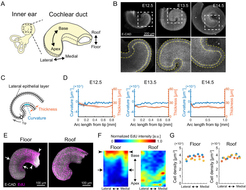
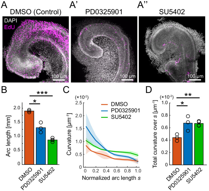
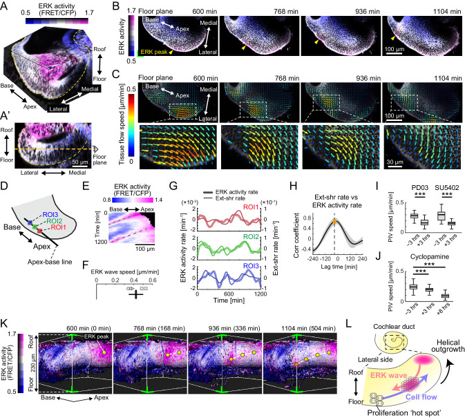
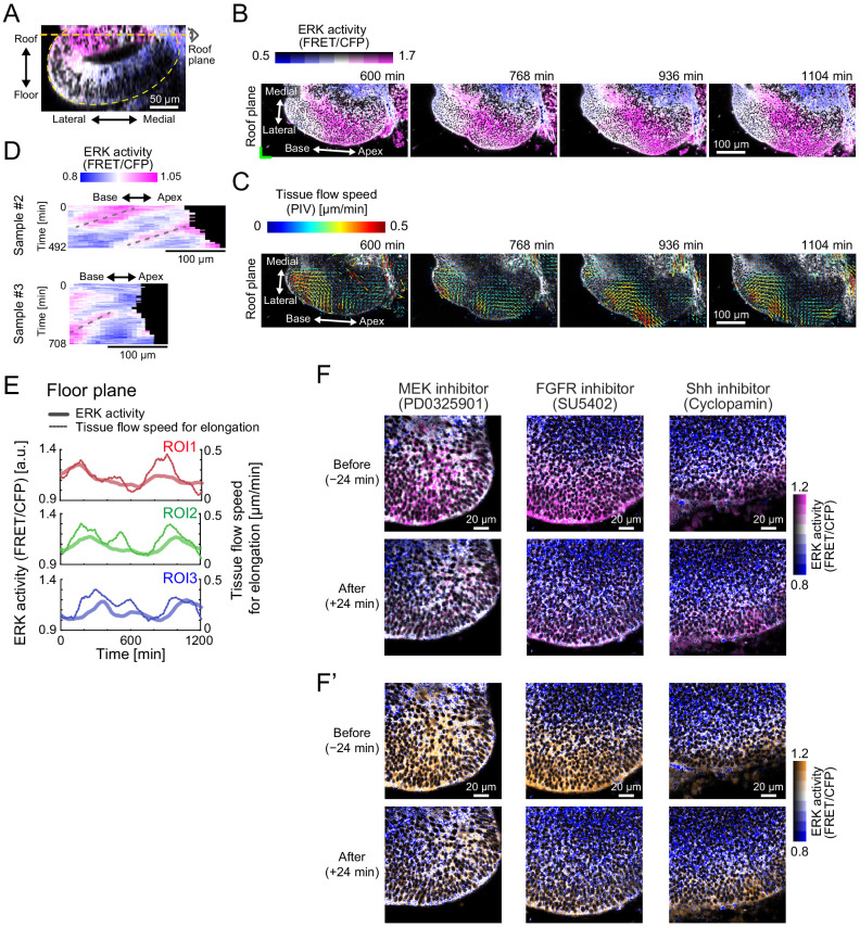
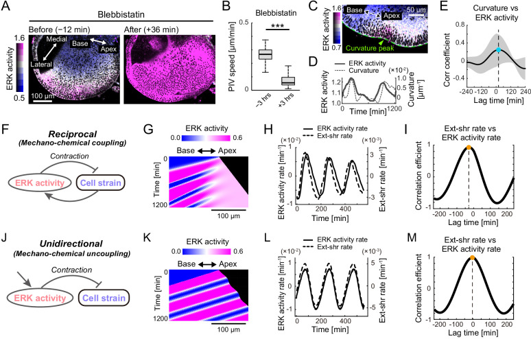
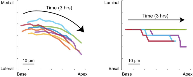
A notable example of spiral architecture in organs is the mammalian cochlear duct, where the morphology is critical for hearing function. Genetic studies have revealed necessary signaling molecules, but it remains unclear how cellular dynamics generate elongating, bending, and coiling of the cochlear duct. Here, we show that extracellular signal-regulated kinase (ERK) activation waves control collective cell migration during the murine cochlear duct development using deep tissue live-cell imaging, Förster resonance energy transfer (FRET)-based quantitation, and mathematical modeling. Long-term FRET imaging reveals that helical ERK activation propagates from the apex duct tip concomitant with the reverse multicellular flow on the lateral side of the developing cochlear duct, resulting in advection-based duct elongation. Moreover, model simulations, together with experiments, explain that the oscillatory wave trains of ERK activity and the cell flow are generated by mechanochemical feedback. Our findings propose a regulatory mechanism to coordinate the multicellular behaviors underlying the duct elongation during development.

Keywords: FRET imaging; MAPK/ERK; developmental biology; mathematical modeling; mechano-chemical feedbacks; morphogenesis; mouse; multicellular flow.


Conflict of interest statement

MI, TT, MM, TH No competing interests declared

Figures

Figure 1.
Figure 1.. Quantification of morphology and cell proliferation in developing murine cochlear duct.
(A) Schematic diagrams showing the tissue axis and labels of the cochlear duct. (B) Immunofluorescence images of anti-E-cadherin staining in the murine developing cochlea from E12.5 to E14.5. The lower rows are magnified images of the dotted squares in the upper rows. Yellow dotted lines represent the edges of the epithelial layer. Scale bar, 200 µm. (C) Schematic diagram showing regions used for morphological quantification. (D) Curvature and thickness as a function of the arc length from the apex tip along the lateral epithelial layer from E12.5 to E14.5. Mean ± standard deviation (s.d.) N = 3. (E) Maximum projection images of stained anti-E-cadherin (white) and EdU (magenta) in the roof and floor region of cochlear duct at E12.5. Representative images showing EdU signals in the cochlear duct are shown. Arrows indicate the region of EdU signal gradient from the medial to the lateral side of the duct. Arrowheads indicate the base region where the EdU intensity is concentrated. Scale bar, 100 µm. (F) Heatmap of the sample-mean of maximum EdU intensity projection in the roof and floor region of the duct. Arrows and arrowheads are the same as in (E). N = 3. Heatmaps of summed and mean intensity projection are shown in Figure 1—figure supplement 1. (G) Cell density distribution along the mediolateral axis in the floor and roof region, respectively. Color indicates the different samples. N = 3.
Figure 1—figure supplement 1.
Figure 1—figure supplement 1.. Heatmaps of EdU (EdU: 5-ethynyl-2′-deoxyuridine, DMSO: dimethyl sulfoxide, PFA: paraformaldehyde, PBS: phosphate-buffered saline) intensity.
Heatmaps of EdU intensity normalized to the maximum value of each graph using various projection methods: maximum intensity projection (left); summed intensity projection (center); and mean intensity projection (right). Note that, in the mean intensity projection, the EdU intensity is subject to increase toward the edge of the cochlear duct because the thickness of the epithelial layer along the projected axis is lesser in the edge than in the middle of the cochlear duct.
Figure 2.
Figure 2.. Pharmacological inhibition of FGFR–ERK signaling axis resulted in the impairment of cochlear duct growth.
(AA’’) Maximum projection images of EdU labeling (magenta) with DAPI (white) nuclear counterstaining over the entire cochleae after 2 days of ex vivo culture from E12.5 in the treatment with DMSO (A), PD0325901 at 1 µM (A’), and SU5402 at 30 µM (A’’). Scale bar, 100 µm. (B) The arc length of the cochlear duct in the treatment with DMSO (red), PD0325901 (blue), and SU5402 (green). N = 3. Two-sample t-test without assuming equal population variances. p=0.023 for DMSO-PD0325901 and p<0.001 for DMSO-SU5402. (C) The curvature of the cochlear duct along the normalized arc length s. Mean ± s.d. N = 3. (D) Total curvature over the normalized arc length in the treatment with DMSO (red), PD0325901 (blue), and SU5402 (green). Two-sample t-test without assuming equal population variances. p=0.021 for DMSO-PD0325901 and p<0.0033 for DMSO-SU5402. ERK: extracellular signal-regulated kinase.
Figure 3.
Figure 3.. Retrograde helical extracellular signal-regulated kinase (ERK) activation waves drive base-to-apex multicellular flow.
(A) 3D ERK activity map in the cochlear duct cultured ex vivo for 1 day from E12.5. (A’) Cross-sectional view (medial–lateral and roof–floor plane) of (A). Orange dotted line indicates the floor plane shown in (B) and (C). Scale bar, 50 µm. (B) Time-lapse snapshots of ERK activity maps in the floor plane. Time indicates the elapsed time of live imaging. Yellow arrowheads indicate the ERK activity peak. Scale bar, 100 µm. (C) Time-lapse snapshots of tissue flow speed obtained by particle image velocimetry in the floor plane. Scale bar, 100 µm. (D) Schematic diagram showing the axis, the apex–base line for kymography, and regions of interests (ROIs). (E) Representative kymograph of ERK activity. The horizontal axis indicates the position on the apex–base line shown in (D), and the vertical axis indicates the elapsed time of live imaging. Dotted lines represent oscillatory waves from the apex to the base. Scale bar, 100 µm. (F) ERK wave speed with mean and s.d. n = 5 from N = 3. (G) Time-series ERK activity rate and extension-shrinkage rate in representative three different ROIs. (H) Cross-correlation between the extension-shrinkage rate and ERK activity rate. n = 12. Mean ± s.d. (I, J) Tissue flow speed before and after the PD0325901 treatment at 1 µM, the SU5402 treatment at 30 µM (I), and the cyclopamine treatment at 30 µM (J). n = 285. Confirmed by N = 2. Two-sample t-test, p<0.001. (K) Time-lapse snapshots of surface-rendered ERK activity maps in the cochlear duct at E12.5. The green corners correspond to the green corner on the images shown in (B) and viewed from the left-bottom corner of (B). Circles indicate the position of ERK activity peaks, and the connecting dotted lines indicate a trace of the peak shift. The timescale is the same as in (B). (L) Schematics for the ERK activity waves and cell flow.
Figure 3—figure supplement 1.
Figure 3—figure supplement 1.. Extracellular signal-regulated kinase (ERK) activity waves and cell flows.
(A) Roof plane (orange dotted line) in the cross-sectional view of 3D ERK activity map in the cochlea at E12.5. Scale bar, 50 µm. (B) Time-lapse snapshots of ERK activity map in the roof plane. Time indicates the elapsed time of live imaging. Scale bar, 100 µm. (C) Time-lapse snapshots of tissue flow speed obtained by the particle image velocimetry in the roof plane. The multicellular flows direct toward the elongation direction around the apex tip despite winding in the region away from the tip in the roof side. Scale bar, 100 µm. (D) Kymograph of ERK activity for the two samples. The horizontal axis indicates the position on the apex–base line, and the vertical axis indicates the elapsed time of live imaging. Dotted lines represent the oscillatory wave trains from the apex to the base. Scale bar, 100 µm. (E) Time-series data of ERK activity and the tissue flow speed for elongation in the three different regions of interests. (F, F’) ERK activity before and after the MEK inhibitor PD0325901 treatment at 1 µM. Scale bar, 20 µm.
Figure 4.
Figure 4.. Extracellular signal-regulated kinase (ERK)-mediated mechanochemical feedback explains cell flow and ERK waves.
(A) ERK activity maps in the floor plane before (−12 min) and after (+36 min) the treatment with 30 µM of blebbistatin. Time indicates the timing of blebbistatin treatment. Scale bar, 100 µm. (B) Tissue flow speed before (−3 hr) and after (+3 hr) blebbistatin treatment. N = 258. Two-sample t-test, p<0.001. (C) Snapshot of the time-lapsed ERK activity map on the lateral side of the cochlear duct (green dotted line), showing coexistence of the ERK activity peak and the tissue curvature peak (green arrowhead). Scale bar, 50 µm. (D) Time-series ERK activity and the tissue curvature in the representative regions of interest. (E) Cross-correlation between the tissue curvature and ERK activity. n = 9. Mean ± s.d. (F) Schematics for the model mechanochemical coupling, in which ERK activity and cell deformation are reciprocally regulated. (G) Kymograph of the ERK activity in the model simulation. Scale bar, 100 µm. (H) Simulated time series of ERK activity rate and extension-shrinkage rate in the mechanochemical coupling regime. (I) Cross-correlation between the extension-shrinkage rate and the ERK activity rate. The lag time is −28 min. (J) Schematics for a counterpart regime of the mechanochemical coupling, in which the ERK activity unidirectionally regulates the cell deformation without closed feedback. (K) Kymograph of the ERK activity in the uncoupling model simulation. Scale bar, 100 µm. (L) Simulated time series of ERK activity rate and extension-shrinkage rate in the uncoupling regime. (D) Cross-correlation between the extension-shrinkage rate and the ERK activity rate. The lag time is −2 min.
Figure 4—figure supplement 1.
Figure 4—figure supplement 1.. Multicellular tracking of the time-lapse images.
A representative trace line for seven neighboring cells around the future prosensory region at E12.5 on the apex–base and medial–lateral plane (left), and the apex–base and luminal–basal plane (right). Color represents different cells. The trace lines do not intersect each other within 3 hr. Scale bar, 10 µm.

References

    1. Aoki K, Kondo Y, Naoki H, Hiratsuka T, Itoh RE, Matsuda M. Propagating wave of ERK activation orients collective cell migration. Developmental Cell. 2017;43:305–317. doi: 10.1016/j.devcel.2017.10.016. - DOI - PubMed
    1. Barrett SD, Bridges AJ, Dudley DT, Saltiel AR, Fergus JH, Flamme CM, Delaney AM, Kaufman M, LePage S, Leopold WR, Przybranowski SA, Sebolt-Leopold J, Van Becelaere K, Doherty AM, Kennedy RM, Marston D, Howard WA, Smith Y, Warmus JS, Tecle H. The discovery of the benzhydroxamate MEK inhibitors CI-1040 and PD 0325901. Bioorganic & Medicinal Chemistry Letters. 2008;18:6501–6504. doi: 10.1016/j.bmcl.2008.10.054. - DOI - PubMed
    1. Bok J, Zenczak C, Hwang CH, Wu DK. Auditory ganglion source of sonic hedgehog regulates timing of cell cycle exit and differentiation of mammalian cochlear hair cells. PNAS. 2013;110:13869–13874. doi: 10.1073/pnas.1222341110. - DOI - PMC - PubMed
    1. Boocock D, Hino N, Ruzickova N, Hirashima T, Hannezo E. Theory of mechanochemical patterning and optimal migration in cell monolayers. Nature Physics. 2021;17:267–274. doi: 10.1038/s41567-020-01037-7. - DOI
    1. Chen P, Johnson JE, Zoghbi HY, Segil N. The role of Math1 in inner ear development: uncoupling the establishment of the sensory primordium from hair cell fate determination. Development. 2002;129:2495–2505. doi: 10.3410/f.1006295.78812. - DOI - PubMed

Publication types