. 2021 Feb 13;12(2):195.
doi: 10.3390/mi12020195.

Shape Fidelity of 3D-Bioprinted Biodegradable Patches

Affiliations

Shape Fidelity of 3D-Bioprinted Biodegradable Patches

Mikail Temirel et al. Micromachines (Basel). .

Abstract

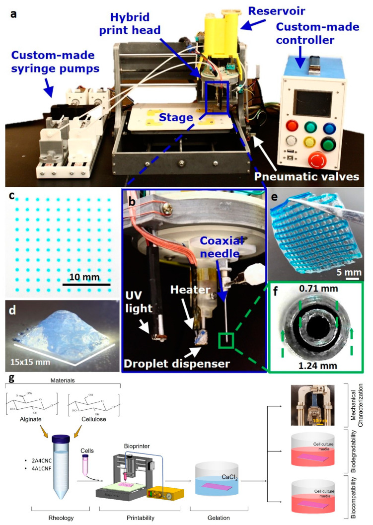
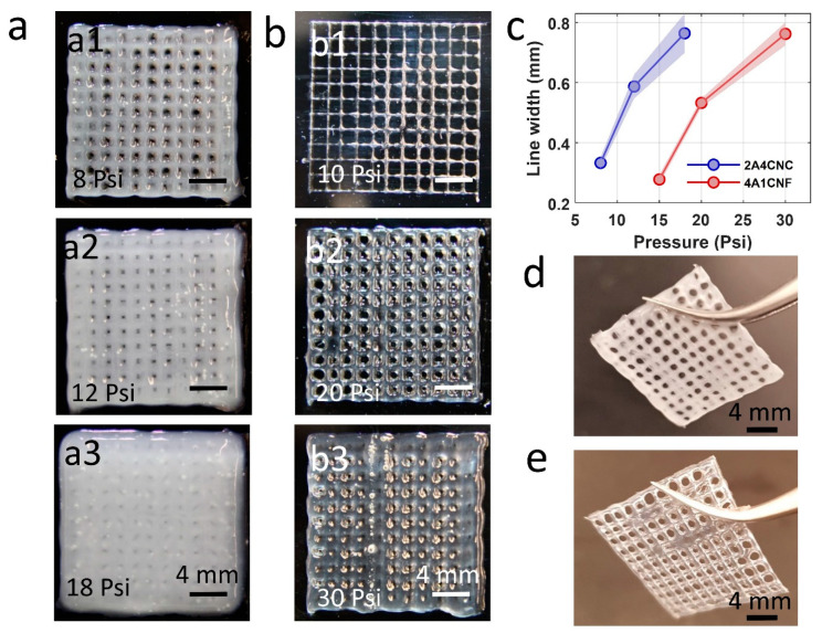
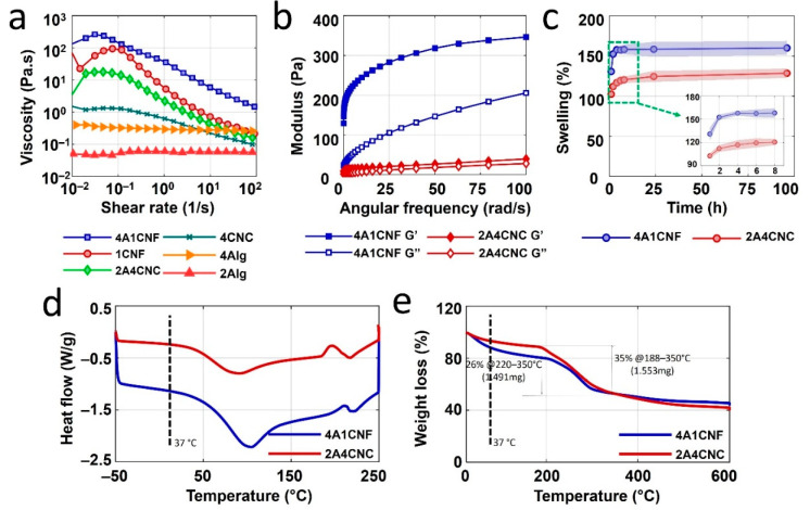
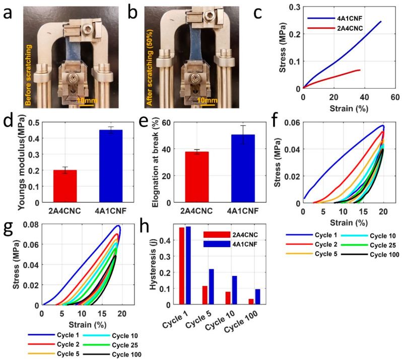
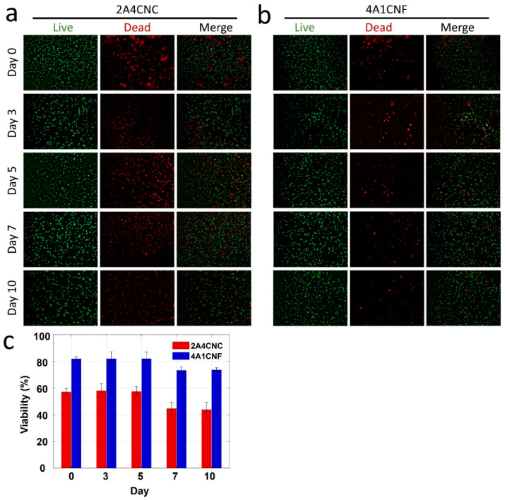
There is high demand in the medical field for rapid fabrication of biodegradable patches at low cost and high throughput for various instant applications, such as wound healing. Bioprinting is a promising technology, which makes it possible to fabricate custom biodegradable patches. However, several challenges with the physical and chemical fidelity of bioprinted patches must be solved to increase the performance of patches. Here, we presented two hybrid hydrogels made of alginate-cellulose nanocrystal (CNC) (2% w/v alginate and 4% w/v CNC) and alginate-TEMPO oxidized cellulose nanofibril (T-CNF) (4% w/v alginate and 1% w/v T-CNC) via ionic crosslinking using calcium chloride (2% w/v). These hydrogels were rheologically characterized, and printing parameters were tuned for improved shape fidelity for use with an extrusion printing head. Young's modulus of 3D printed patches was found to be 0.2-0.45 MPa, which was between the physiological ranges of human skin. Mechanical fidelity of patches was assessed through cycling loading experiments that emulate human tissue motion. 3D bioprinted patches were exposed to a solution mimicking the body fluid to characterize the biodegradability of patches at body temperature. The biodegradation of alginate-CNC and alginate-CNF was around 90% and 50% at the end of the 30-day in vitro degradation trial, which might be sufficient time for wound healing. Finally, the biocompatibility of the hydrogels was tested by cell viability analysis using NIH/3T3 mouse fibroblast cells. This study may pave the way toward improving the performance of patches and developing new patch material with high physical and chemical fidelity for instant application.

Keywords: alginate; bioprinter; biopriting; cellulose nanocrystal; cellulose nanofiber; extrusion; fidelity.


Conflict of interest statement

The authors declare no conflict of interest.

Figures

Figure 1
Figure 1
(af) Images of our custom hybrid bioprinter developed previously and given here for completeness. Reproduced with permission from [51]. The custom printer includes a cell-laden droplet dispenser for inkjet 3D bioprinting, a UV light source for photo-crosslinking, and a coaxial head for extrusion-based 3D bioprinting. (g) Schematic illustration of the experimental workflow in the current article.
Figure 2
Figure 2
Printability of two hybrid bioink formulations using custom-made bioprinter. (a) Representative images of 3D printed 16-layers and 20 × 20 mm square grid pattern for 2A4CNC (2% Alginate and 4% Cellulose Nanocrystals) bioink. Three different air pressures were tested to find optimum pneumatic air pressure. (b) Representative images of 3D printed grid pattern with 4A1CNF (4% Alginate and 1% TEMPO oxidized Cellulose Nanofiber) under three different air pressures. (c) Line thickness printed by extrusion at various air pressures, showing the effect of air pressure on the filament width. (d) Representative images of 2-layers grid pattern after 2 min crosslinking in calcium with an optimum air pressure of 12 PSI for 2A4CNC bioink and (e) optimum air pressure of 20 PSI for 4A1CNF.
Figure 3
Figure 3
Rheological and thermal characterization of bioinks. (a) The viscosity of two hybrid bioinks formulation (4A1CNF, 2A4CNC) and their separate components (4A, 1CNF, 2A, and 4CNC) as a function of shear rate. (b) Storage modulus (G’) and loss modulus (G’’) of two bioink formulations (4A1CNF and 2A4CNC). (c) Swelling (water absorbance) of dried patches made with these two bioinks over up to 96 h. Differential scanning calorimetry (DSC) analysis results (d) and thermogravimetric analysis (TGA) results (e) of freeze-dried 4A1CNF and 2A4CNC samples.
Figure 4
Figure 4
Mechanical characterization of 3D printed patches. (a,b) Images of 4A1CNF before stretching and 50% elongation under tensile tests. (c) Stress-strain curve of two samples under a ramped fore rate of 0.1 N/min. (d) Young’s modulus from the slope in the initial linear region of the stress-strain curve for two samples. (e) Maximum elongation of sample right before the samples fractured. Cycling loading in DI water to assess the hysteresis, deformation over cycling that mimics the movement in the skin for (f) 2A4CNC and (g) 4A1CNF. The sample was scratched repeatedly for 100 cycles at strain ramp 10%/min to 20% strain. (h) Hysteresis versus the number of cycling from the stress-strain curve of the inside area of loading and unloading.
Figure 5
Figure 5
In vitro degradation of printed constructs. (a) Weight loss (%) of two samples in cell culture media containing Dulbecco’s modified Eagle’s medium (DMEM) with 10% fetal bovine serum (FBS) over a month. (b) The compressive modulus of samples (l × w × h = 10 × 10 × 2 mm) was compared with the time of exposure to the cell culture media for 5-day periods up to one month. Inlet: a representative image of a sample undergoing a compression test by a dynamic mechanical analyzer (DMA). Statistical differences were calculated by one-way ANOVA test for multiple comparisons (p < 0.0001). (c) Pictorial representative images of washed and freeze-dried samples after withdrawal from the media in 5 days period. Error bars represent the standard deviation of 3 independent measurements. Scanning electron microscope (SEM) images of freeze-dried (d) 2A4CNC on day 0, (e) 2A4CNC after 10-day degradation, (f) 4A1CNF on day 0, and (g) 4A1CNF after 10-day degradation.
Figure 6
Figure 6
Characterization of cell viability. Fluorescence images of National Institutes of Health (NIH) 3T3 mouse embryonic fibroblast cells in (a) 2A4CNC and (b) 4A1CNF hydrogels, showing the cell viability after day 0, 3, 5, 7, and 10. The green-stained (Calcein AM, 0.5 µL/mL) cell represents the live-cell shown in the first column. Red-stained (ethidium homodimer 1, 2 µL/mL) cell represents the dead cell shown in the second column. The third column shows the merge of live and dead cells. (c) Quantification of the cell viability from live/dead image analysis. Statistical differences were calculated by one-way ANOVA test and t-test for multiple and two samples comparison (p < 0.0001). Error bars represent the standard deviation of three independent measurements.

References

    1. Collection A.S. Tissue engineering. J. Cell. Biochem. 1990;44:227–256. doi: 10.1002/jcb.240440806. - DOI
    1. Knowlton S., Onal S., Yu C.H., Zhao J.J., Tasoglu S. Bioprinting for cancer research. Trends Biotechnol. 2015;33:504–513. doi: 10.1016/j.tibtech.2015.06.007. - DOI - PubMed
    1. Tasoglu S., Demirci U. Bioprinting for stem cell research. Trends Biotechnol. 2013;31:10–19. doi: 10.1016/j.tibtech.2012.10.005. - DOI - PMC - PubMed
    1. Knowlton S., Anand S., Shah T., Tasoglu S. Bioprinting for Neural Tissue Engineering. Trends Neurosci. 2018;41:31–46. doi: 10.1016/j.tins.2017.11.001. - DOI - PubMed
    1. Torikai K., Ichikawa H., Hirakawa K., Matsumiya G., Kuratani T., Iwai S., Saito A., Kawaguchi N., Matsuura N., Sawa Y. A self-renewing, tissue-engineered vascular graft for arterial reconstruction. J. Thorac. Cardiovasc. Surg. 2008;136:7–11. doi: 10.1016/j.jtcvs.2007.06.039. - DOI - PubMed

LinkOut - more resources