. 2021 Feb 13;13(4):562.
doi: 10.3390/polym13040562.

Enhancing Mechanical Properties of Polymer 3D Printed Parts

Affiliations

Enhancing Mechanical Properties of Polymer 3D Printed Parts

Catalin Gheorghe Amza et al. Polymers (Basel). .

Abstract

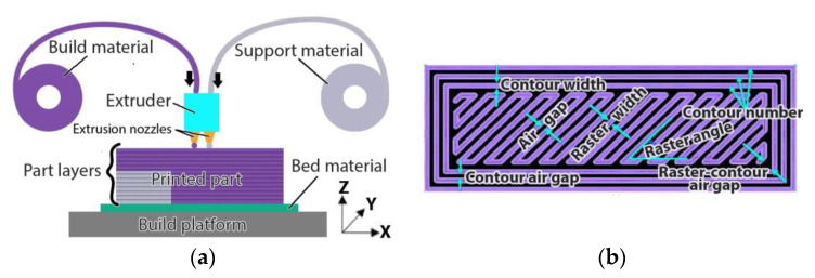
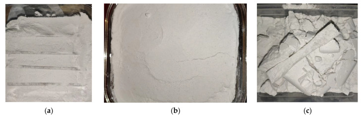
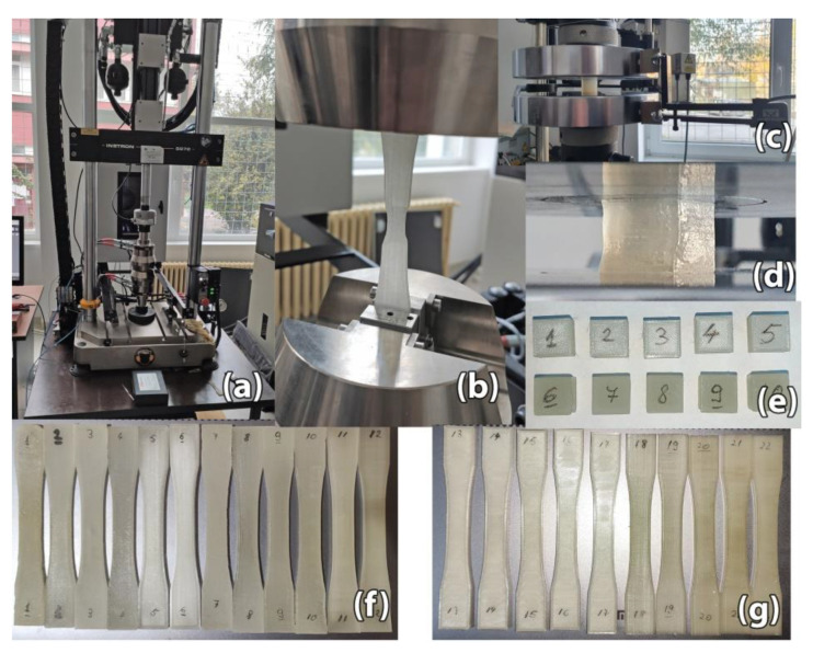
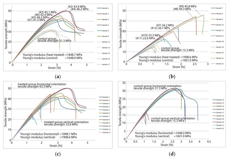
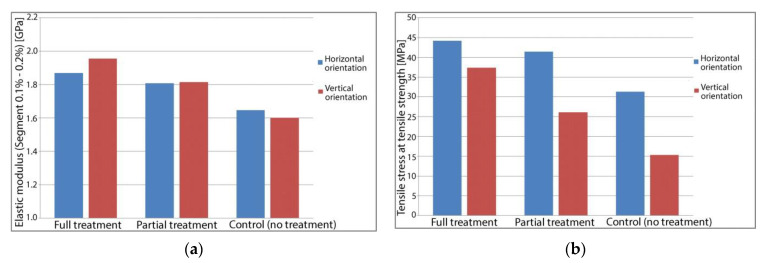
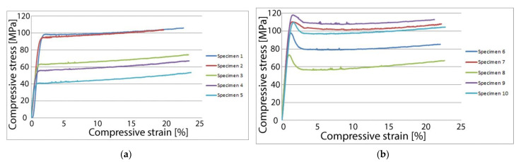
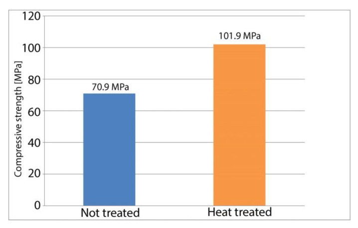
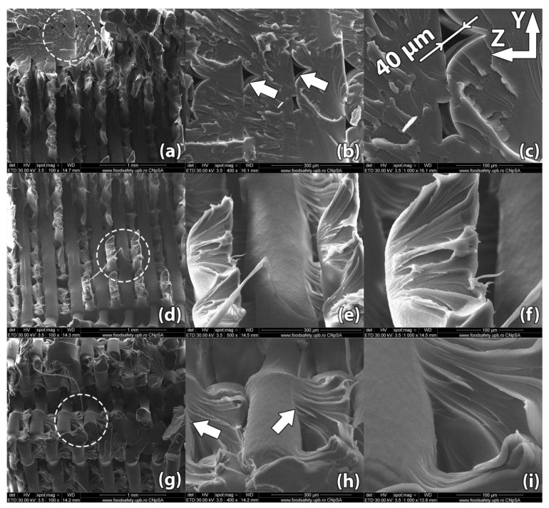
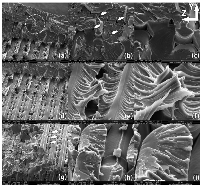
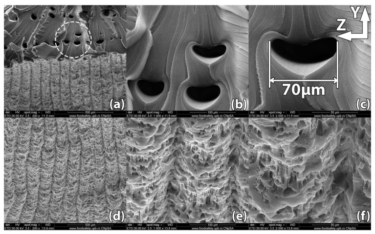
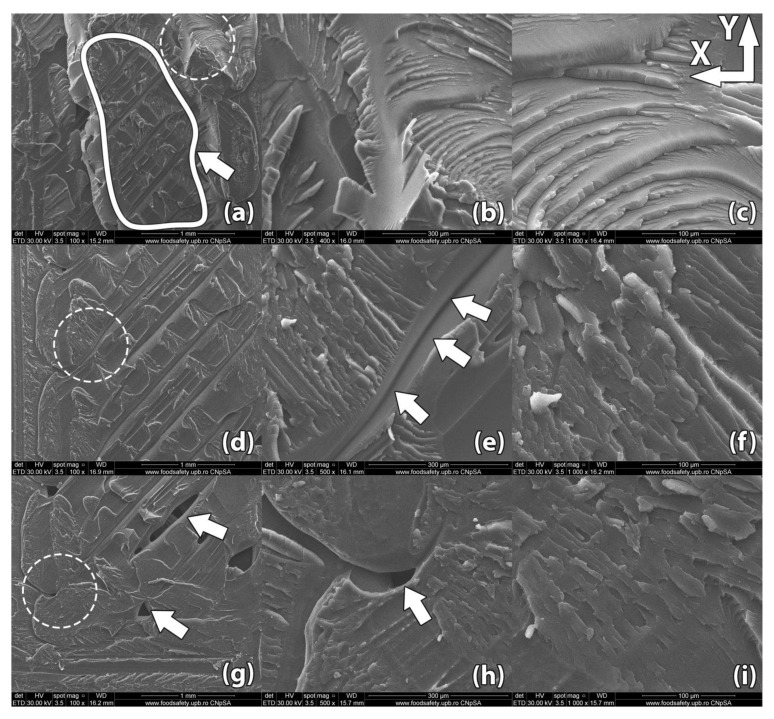
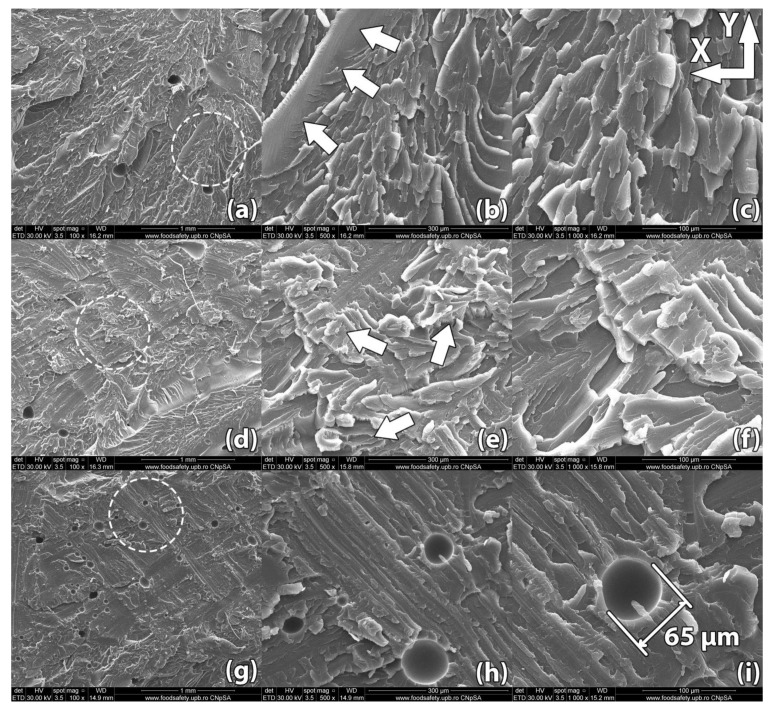
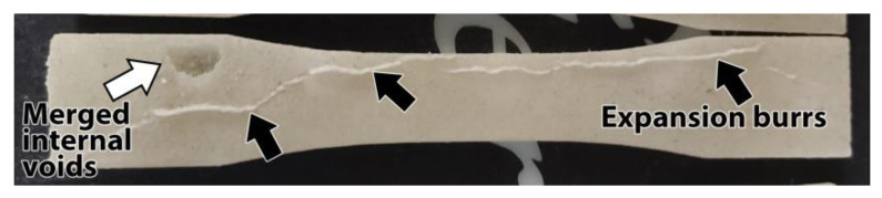
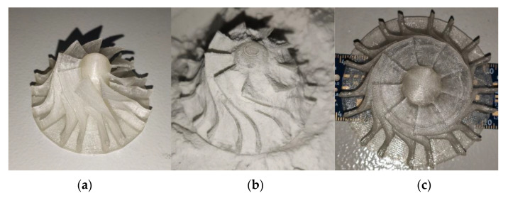
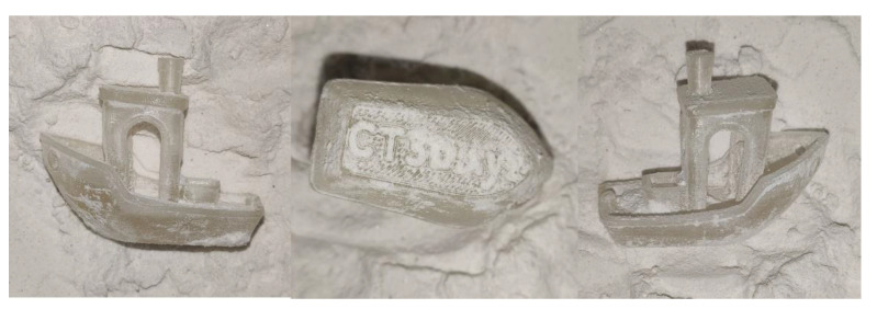
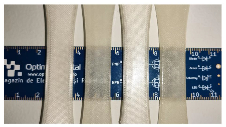
Parts made from thermoplastic polymers fabricated through 3D printing have reduced mechanical properties compared to those fabricated through injection molding. This paper analyzes a post-processing heat treatment aimed at enhancing mechanical properties of 3D printed parts, in order to reduce the difference mentioned above and thus increase their applicability in functional applications. Polyethylene Terephthalate Glycol (PETG) polymer is used to 3D print test parts with 100% infill. After printing, samples are packed in sodium chloride powder and then heat treated at a temperature of 220 °C for 5 to 15 min. During heat treatment, the powder acts as support, preventing deformation of the parts. Results of destructive testing experiments show a significant increase in tensile and compressive strength following heat treatment. Treated parts 3D printed in vertical orientation, usually the weakest, display 143% higher tensile strength compared to a control group, surpassing the tensile strength of untreated parts printed in horizontal orientation-usually the strongest. Furthermore, compressive strength increases by 50% following heat treatment compared to control group. SEM analysis reveals improved internal structure after heat treatment. These results show that the investigated heat treatment increases mechanical characteristics of 3D printed PETG parts, without the downside of severe part deformation, thus reducing the performance gap between 3D printing and injection molding when using common polymers.

Keywords: 3D printed; PETG; polymer remelting.


Conflict of interest statement

The authors declare no conflict of interest. The funders had no role in the design of the study; in the collection, analyses, or interpretation of data; in the writing of the manuscript, or in the decision to publish the results.

Figures

Figure 1
Figure 1
Material extrusion 3D printing: (a) Process schematic—the extruder and the build platform move relative to one another in the XY plane in order to deposit a horizontal layer and in the Z direction in order to position for the next layer; (b) Process parameters that influence horizontal layer deposition.
Figure 2
Figure 2
Heat treatment: (a) Samples being powder-packed in the borosilicate glass recipient; (b) Recipient with packed powder; (c) 3D printed samples after heat treatment.
Figure 3
Figure 3
Destructive tests: (a) Instron 8872 machine; (b) Tensile strength testing; (c) Instron 8801 universal testing machine; (d) Compressive strength testing; (e) Cubic samples for compressive strength testing. Samples #1–#5 belong in the control group while samples #6–#10 are in the heat treatment group; (f) Heat treated samples for tensile strength testing. Samples #1–#4 and #7–#10 have undergone full heat treatment while samples #5–#6 and #11–#12 went through partial heat treatment. Samples #1–#6 are printed in horizontal orientation while #7–#12 are printed in vertical orientation; (g) Control group for tensile strength testing. Samples #13–#17 are printed in horizontal orientation while #18–#22 are printed in vertical orientation.
Figure 4
Figure 4
Tensile strength testing results: (a) Samples printed horizontally treated vs. control group; (b) Samples printed vertically treated vs. control group; (c) Treated samples printed vertically vs. horizontally; (d) Control group samples, printed with the same set of parameters but not heat treated, showing the poorest mechanical characteristics.
Figure 5
Figure 5
Tensile strength testing results—process averages: (a) Average Young’s Modulus for tested parts; (b) Average tensile strength for tested parts.
Figure 6
Figure 6
Compressive strength testing results: (a) Compressive strength of the 5 samples from the control group varied between 41.3 MPa and 98.4 MPa; (b) Compressive strength of the 5 samples from the heat-treated group varied between 73.4 MPa and 118.1 MPa.
Figure 7
Figure 7
Compressive strength—sample averages.
Figure 8
Figure 8
Scanning Electron Microscopy image of a control sample printed in horizontal orientation (sample #14): (ac) Due to the raster angle changing from 45° to −45° for each horizontal layer, internal voids 20–50 µm in width remain at the interface of the deposited filaments; (df) Upon rupture, the sample presents fracture lines along the deposited layers in a zig-zag pattern specific to the −45°/45° infill used in part manufacturing; (gi) Interlayer fusion is limited to the areas where the deposited filaments of two horizontal layers intersect.
Figure 9
Figure 9
Scanning Electron Microscopy image of a sample printed in horizontal orientation (sample #05). (ac) Due to the raster angle changing from 45° to −45° for each horizontal layer, internal voids remain at the interface of the deposited filaments but their size is significantly reduced compared to the control sample, ranging between 15 µm and 30 µm in width; (df) Upon rupture, the sample presented fracture lines along the deposited layers in a zig-zag pattern specific to the −45°/45° infill used in part manufacturing; (gi). Interlayer fusion is increased compared to the control sample.
Figure 10
Figure 10
Scanning Electron Microscopy image of a sample printed in horizontal orientation (sample #03): (ac) Merged internal voids of an obloid shape, 50–75 µm in length, form at the interface between raster angles changes; (df) The exterior surface of the part shows micro-voids formed during the heat treatment at the interface between the sample wall and the supporting powder. These voids are 5–10 µm in size.
Figure 11
Figure 11
Scanning Electron Microscopy image of a control sample printed in vertical orientation (sample #18): (ac) Upon rupture, the sample presented uniform fracture lines along the deposited horizontal layers, showing poor adhesion at the layer level; (df) Internal gaps between deposited filaments remained embedded in the part, weakening the structure; (gi) Bigger internal voids remained embedded in the part in the area where the raster angle changes from one layer to another.
Figure 12
Figure 12
Scanning Electron Microscopy image of a sample printed in vertical orientation (sample #09): (ac) Unlike the control sample, the linear voids between deposited filaments have been filled during the heat treatment; (df) Upon rupture, the sample presented fracture lines along multiple horizontal layers, indicating superior layer adhesion; (gi) Spherical pockets of air 10–70 µm in diameter remain inside the part.
Figure 13
Figure 13
Defects appearing in heat treated part. Black arrows point to expansion burrs that occurred due to inadequate packing of powder support material. The white arrow highlights a large internal void.
Figure 14
Figure 14
Images of a 3D printed small turbine wheel: before treatment; (a) and after heat treatment (b,c).
Figure 15
Figure 15
Images of a 3DBenchy (all instances shown are after heat treatment).
Figure 16
Figure 16
Visual changes observed in optical properties after heat treatment of horizontal orientation 3D printed parts. Lighter parts are untreated samples from the control group and darker parts are samples after full heat treatment. No other processing was done to the samples.

References

    1. Hull C.W. Apparatus for Production of Three-Dimensional Objects by Stereolithography. No. 4575330. U.S. Patent. 1984 Aug 8;
    1. Crump S.S. Apparatus and Method for Creating Three-Dimensional Object. No. 5121329. U.S. Patent. 1989 Oct 30;
    1. Steenhuis H.-J., Pretorius L. Consumer additive manufacturing or 3D printing adoption: An exploratory study. J. Manuf. Technol. Manag. 2016;27:990–1012. doi: 10.1108/JMTM-01-2016-0002. - DOI
    1. Sepasgozar S.M.E., Shi A., Yang L., Shirowzhan S., Edwards D.J. Additive Manufacturing Applications for Industry 4.0: A Systematic Critical Review. Buildings. 2020;10:231. doi: 10.3390/buildings10120231. - DOI
    1. MarketsandMarkets . Market. Research Report: Industrial 3D Printing Market by Offering, Application, Process, Technology, Industry and Geography—Global Forecast to 2025. MarketsandMarkets; Northbrook, IL, USA: 2020. Report ID SE 4293.

LinkOut - more resources