. 2021 Feb 25;21(5):1618.
doi: 10.3390/s21051618.

A Dynamic Motion Analysis of a Six-Wheel Ground Vehicle for Emergency Intervention Actions

Affiliations

A Dynamic Motion Analysis of a Six-Wheel Ground Vehicle for Emergency Intervention Actions

Lucian Ștefăniță Grigore et al. Sensors (Basel). .

Abstract

To protect the personnel of the intervention units operating in high-risk areas, it is necessary to introduce (autonomous/semi-autonomous) robotic intervention systems. Previous studies have shown that robotic intervention systems should be as versatile as possible. Here, we focused on the idea of a robotic system composed of two vectors: a carrier vector and an operational vector. The proposed system particularly relates to the carrier vector. A simple analytical model was developed to enable the entire robotic assembly to be autonomous. To validate the analytical-numerical model regarding the kinematics and dynamics of the carrier vector, two of the following applications are presented: intervention for extinguishing a fire and performing measurements for monitoring gamma radiation in a public enclosure. The results show that the chosen carrier vector solution, i.e., the ground vehicle with six-wheel drive, satisfies the requirements related to the mobility of the robotic intervention system. In addition, the conclusions present the elements of the kinematics and dynamics of the robot.

Keywords: dynamic; kinematic; mobile robotics; mobility; rescue; sensors; wheel.


Conflict of interest statement

The authors declare no conflict of interest.

Figures

Figure 1
Figure 1
The terrestrial 6 × 6 robot developed for identifying, monitoring, and intervening in risky areas. The structural elements of the robot include the command-and-control system, the battery system, and the weather station.
Figure 2
Figure 2
Schematic representation of the three major classes of command-and-control systems of terrestrial robots. For ongoing research, on the use of 6 × 6 terrestrial robots for the purpose of identification, monitoring and intervention in risk areas, we proposed that of the three versions: (a) direct or manual control; (b) mixed control; (c) supervised control, to use version (b).
Figure 3
Figure 3
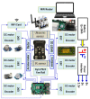
The control and command architecture of the studied robot including obstacle detection (ultrasonic and infrared (IR) sensors); orientation (tri-axial accelerometer and global positioning system (GPS)), gyroscope (pitch, yaw, and roll), compass; DC motor encoder, Electronic Speed Controller (ESC); Pixhawk controller, Raspberry Pi 4 controller and NVIDIA Jetson Nano; power system, and Wi-Fi communication system.
Figure 4
Figure 4
Schematic representation of the propulsion system of the 6 × 6 robot for emergency situations consists of six motors with a gearbox, six wheels with rubber tires, and a nodular balloon inflated with air for more efficient damping of the unevenness of the route during movement of the robot.
Figure 5
Figure 5
The 6 × 6 kinematic diagrams of the robot showing the following essential characteristics for a simple and fast analysis of the robot kinematics: the six driving wheels are not steering wheels; turns are made by changing the rotational speeds of the six wheels; cornering radii varied depending on the rotational speed of the drive wheels and the indices of adhesion to the ground, the slip indices. If the movement was rectilinear, the decomposition of the speed was uniform only for the ideal conditions of movement; the ground contact of the balloon of the wheels was related to the pressure in the balloon. The weight of the robot and the position of the center of gravity may be altered, in particular, by the operating platforms.
Figure 6
Figure 6
Schematic of the 2D dynamics of the 6 × 6 robot, which had some specificities related to the choice of travel mode. The ground contact spots of the six wheels were identical. Working conditions are ideal when Md = Mr (Md—motor torque; Mr—resistant moment). The geometric center of the contact spots (yellow dots) during the turn is represented outside the geometric center of the contact spots. This representation suggests that progression in the field is influenced by different coefficients and that each operational platform can create an additional balance.
Figure 7
Figure 7
A schematic of the 3D dynamics of the 6 × 6 robot showing the elements that influence the dynamic characteristics of a land vehicle: air resistance, friction force, robot weight, center of gravity position, wheel radius, and slope angle. The following figures will highlight other elements that contribute to influencing the law of motion of the robot.
Figure 8
Figure 8
Schematic of the escalation of a step-type obstacle by the robot. To ensure good ability to climb the step, the front, and middle wheels to be in permanent contact with the step to be climbed. It is not mandatory to have this situation; depending on the geometry of the workspace, energy consumption can increase, which affects the autonomy of movement. The robot was designed to move without being powered by a cable.
Figure 9
Figure 9
The variation in βgrd as a function of the center of mass for h = 0.20 m (where h is the height of the step obstacle); the height of the step is constant. If the step to be scaled has a different height, the values in the graph will change. The pressure value of the wheel tires was not considered in this simulation.
Figure 10
Figure 10
The variation in the μ necessary for climbing a slope following the simulation using Equations (15)–(19). For the geometric characteristics of the robot and the total minimum adhesion coefficient, the robot could climb a step under the conditions of a CG (center of gravity of the robot) with a height = 0.20 m.
Figure 11
Figure 11
The variation in the necessary MtNm as a function of the tilt angle of the slope.
Figure 12
Figure 12
The variation in the μ necessary to cross an obstacle as a function of its height. The data used for the calculations are found in Appendix A and Table A1. Given the geometric characteristics of the towing robot and the mobile platform, and that changes are possible depending on the dimensions of the operational platforms, the robot can be used for different missions; we consider the data used to be sufficient: (a) crossing with bridge 1; (b) crossing with bridges 1 and 2.
Figure 13
Figure 13
The variation in the FtN necessary for crossing an obstacle as a function of its height. The explanations presented in Figure 12 also apply here: (a) crossing with bridge 1; (b) crossing with bridges 1 and 2.
Figure 14
Figure 14
Schematic of braking while descending a longitudinal slope. The dynamics of the robot during braking are much more suggestive when the process is diagrammed during the descent of a slope. In this case, two other notions intervene: a, deceleration when braking; Rf, friction force.
Figure 15
Figure 15
The variation in the maximum deceleration at braking on a 30º slope as a function of the center of mass.
Figure 16
Figure 16
Basic reference system for inertial navigation.
Figure 17
Figure 17
The dynamic characteristics of the 6 × 6 robot when braking on the slope, determined with the help of an inertial sensor system.
Figure 18
Figure 18
Representation of the displacement of the coordinate system with the help of Euler’s angles.
Figure 19
Figure 19
The evolution of the longitudinal acceleration while braking on a slope, determined with the help of a GPS sensor system.
Figure 20
Figure 20
Fire extinguishing system with two fire extinguishers and mechanism for maintaining the pressure of the extinguishing-type powder (Florex, E.12, Carbo, based on KHCO3).
Figure 21
Figure 21
Extinguishing jet performance. The fire was maintained by a pile of cotton cloths soaked in liquid fuel or diesel. When the smoke became sufficient and the wind direction changed toward the robot, the smoke sensors triggered the fire extinguishing system. The system was constructed with the help of two inert gas fire extinguishers.
Figure 22
Figure 22
Environmental samples taken with an Arduino-controlled weather station p/n 80,422. The values recorded by the weather station correspond to a summer period.
Figure 23
Figure 23
Air temperature simulation for an output speed of 10 m/s. The numerical simulation was performed using the finite element simulation application Solid Works.
Figure 24
Figure 24
Thermal study for target C (front view) direct contact with the flame at a temperature above 150 °C. Plate thickness: 4 mm, material: 316 L stainless steel, holding time: 4 min, and a concave shape.
Figure 25
Figure 25
Robotic system with an operational vector used to determine gamma radiation. The experiments were recorded at Titu Maiorescu University in Bucharest.
Figure 26
Figure 26
Gamma radiation measurement with a Canberra dosimeter and spectrometer. The recorded values were part of the background of natural radiation. The values that stood out were specific to potassium. The purpose of data collection was to demonstrate the robot’s ability to perform different missions.

References

    1. Hoeppe P. Trends in weather related disasters—Consequences for insurers and society. Weather Clim. Extrem. 2016;11:70–79. doi: 10.1016/j.wace.2015.10.002. - DOI
    1. Fire and Rescue Authorities Operational Guidance Generic Risk Assessment 3.10 Fighting Fires in Petrochemical Plant and Pipelines. [(accessed on 24 February 2021)]; Available online: https://assets.publishing.service.gov.uk/government/uploads/system/uploa....
    1. Nuță I. Ph.D. Thesis. Military Technical Academy “FERDINAND I”; Bucharest, Romania: 2013. Contributions to the Development and Improvement of Emergency Intervention Techniques; p. 352.
    1. Virginia Tech Takes on Department of Defense Challenge to Build Disaster-Response Robots. [(accessed on 24 February 2021)]; Available online: https://vtnews.vt.edu/articles/2012/10/102412-engineering-thorrobotannou...
    1. Kurvinen K., Smolander P., Pöllänen R., Kuukankorpi S., Kettunen M., Lyytinen J. Design of a radiation surveillance unit for an unmanned aerial vehicle. J. Environ. Radioact. 2005;81:1–10. doi: 10.1016/j.jenvrad.2004.10.009. - DOI - PubMed

LinkOut - more resources