

Microfabrication with Very Low-Average Power of Green Light to Produce PDMS Microchips
- PMID: 33670467
- PMCID: PMC7921959
- DOI: 10.3390/polym13040607
Microfabrication with Very Low-Average Power of Green Light to Produce PDMS Microchips
Abstract
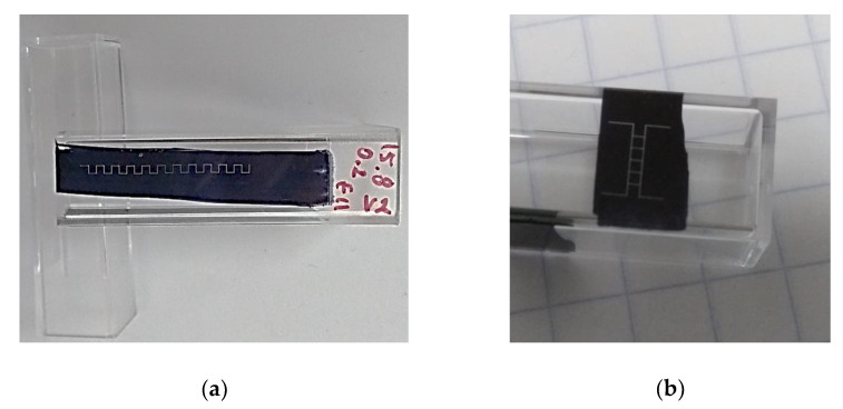
In this article, we show an alternative low-cost fabrication method to obtain poly(dimethyl siloxane) (PDMS) microfluidic devices. The proposed method allows the inscription of micron resolution channels on polystyrene (PS) surfaces, used as a mold for the wanted microchip's production, by applying a high absorption coating film on the PS surface to ablate it with a focused low-power visible laser. The method allows for obtaining micro-resolution channels at powers between 2 and 10 mW and can realize any two-dimensional polymeric devices. The effect of the main processing parameters on the channel's geometry is presented.
Keywords: PDMS devices; laser ablation; low-cost fabrication tool; microfabrication; polymeric microchip.
Conflict of interest statement
The authors declare no conflict of interest.
Figures


Similar articles
-
Fabricating smooth PDMS microfluidic channels from low-resolution 3D printed molds using an omniphobic lubricant-infused coating.Anal Chim Acta. 2018 Feb 13;1000:248-255. doi: 10.1016/j.aca.2017.11.063. Epub 2017 Nov 30. Anal Chim Acta. 2018. PMID: 29289317
-
Direct Micromachining of Microfluidic Channels on Biodegradable Materials Using Laser Ablation.Polymers (Basel). 2017 Jun 23;9(7):242. doi: 10.3390/polym9070242. Polymers (Basel). 2017. PMID: 30970919 Free PMC article.
-
Simple, rapid and, cost-effective fabrication of PDMS electrophoresis microchips using poly(vinyl acetate) as photoresist master.Electrophoresis. 2017 Jan;38(2):250-257. doi: 10.1002/elps.201600209. Epub 2016 Aug 30. Electrophoresis. 2017. PMID: 27377397
-
A practical guide to rapid-prototyping of PDMS-based microfluidic devices: A tutorial.Anal Chim Acta. 2020 Oct 23;1135:150-174. doi: 10.1016/j.aca.2020.09.013. Epub 2020 Sep 11. Anal Chim Acta. 2020. PMID: 33070852 Review.
-
Polymer Microfluidics: Simple, Low-Cost Fabrication Process Bridging Academic Lab Research to Commercialized Production.Micromachines (Basel). 2016 Dec 10;7(12):225. doi: 10.3390/mi7120225. Micromachines (Basel). 2016. PMID: 30404397 Free PMC article. Review.
Cited by
-
Ultrahigh-Throughput Enzyme Engineering and Discovery in In Vitro Compartments.Chem Rev. 2023 May 10;123(9):5571-5611. doi: 10.1021/acs.chemrev.2c00910. Epub 2023 May 1. Chem Rev. 2023. PMID: 37126602 Free PMC article. Review.
-
One-Step Fabrication of Microfluidic Channels in Polydimethylsiloxane: Influence of Laser Power on Channel Formation.Micromachines (Basel). 2025 Feb 28;16(3):282. doi: 10.3390/mi16030282. Micromachines (Basel). 2025. PMID: 40141893 Free PMC article.
References
Grants and funding
LinkOut - more resources
Full Text Sources
Other Literature Sources
