Review
. 2021 Feb 18;13(4):608.
doi: 10.3390/polym13040608.

Recent Advances in UHMWPE/UHMWPE Nanocomposite/UHMWPE Hybrid Nanocomposite Polymer Coatings for Tribological Applications: A Comprehensive Review

Affiliations
Review

Recent Advances in UHMWPE/UHMWPE Nanocomposite/UHMWPE Hybrid Nanocomposite Polymer Coatings for Tribological Applications: A Comprehensive Review

Mohammed Abdul Samad. Polymers (Basel). .

Abstract

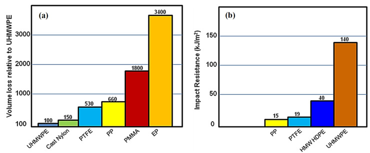
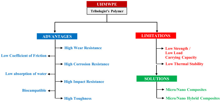
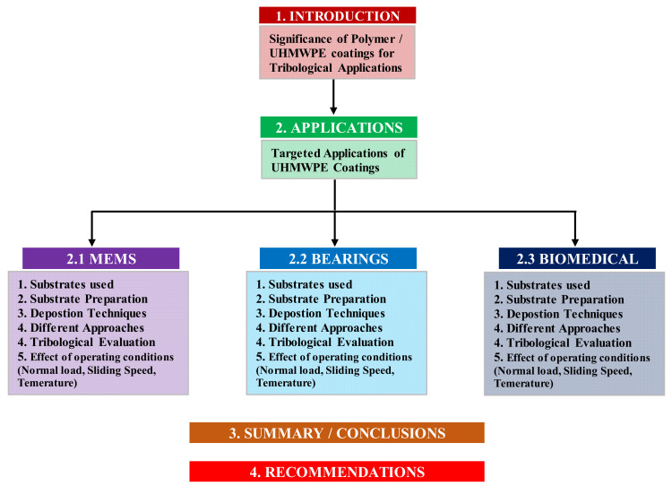
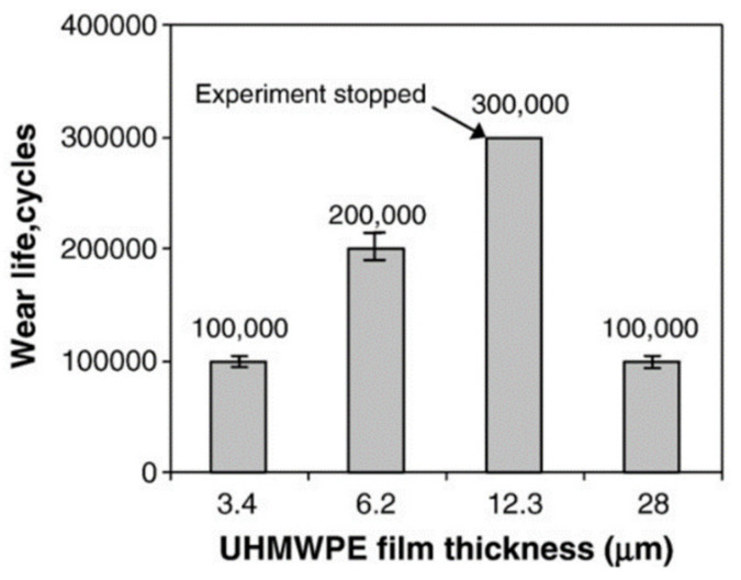
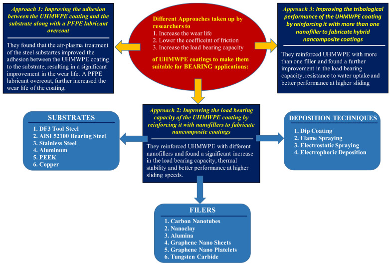
In the recent past, polymer coatings have gained the attention of many researchers due to their low cost, their ability to be coated easily on different substrates, low friction and good anti-corrosion properties. Various polymers such as polytetrafluroethylene (PTFE), polyether ether ketone (PEEK), polymethylmethacrylate (PMMA), polyurethane (PU), polyamide (PA), epoxy and ultra-high molecular weight polytheylene (UHMWPE) have been used to develop these coatings to modify the surfaces of different components to protect them from wear and corrosion. However, among all these polymers, UHMWPE stands out as a tribologist's polymer due to its low friction and high wear resistance. These coatings have found their way into applications ranging from microelectro mechanical systems (MEMS) to demanding tribological applications such as bearings and biomedical applications. Despite its excellent tribological properties, UHMWPE suffers from limitations such as low load bearing capacity and low thermal stability. To overcome these challenges researchers have developed various routes such as developing UHMWPE composite and hybrid composite coatings with several types of nano/micro fillers, developing composite films system and developing dual film systems. The present paper is an effort to summarize these various routes adopted by different researchers to improve the tribological performance of UHMWPE coatings.

Keywords: UHMWPE coatings; friction; tribology; wear.


Conflict of interest statement

The author declares no conflict of interest.

Figures

Figure 1
Figure 1
(a) Volume loss of most common polymers relative to UHMWPE (b) Impact resistance of UHMWPE as compared to other polymers. Adapted from [24].
Figure 2
Figure 2
UHMWPE as a Tribo-Material: Advantages, Limitations and Solutions.
Figure 3
Figure 3
A bird’s view of the arrangement of this article.
Figure 4
Figure 4
Wear life for different UHMWPE thicknesses for Si/DLC/UHMWPE. Data are averages of three repeated tests. For 12.3 μm thick film there was no failure at 300,000 cycles of sliding when the experiments were stopped due to long test duration [54]. Reproduced with permission from Minn, M. and Sinha, S.K., Surface and Coating Technology; published by Elsevier, 2008.
Figure 5
Figure 5
(i) Wear life of Si coated with different composite films. [(ac)]–Optical images of the wear tracks and [(df)]–Optical images of the counterface Si3N4 balls after a wear test for 300,000 cycles on UHMWPE coatings deposited on TiN, DLC57 and DLC70 layers, respectively [55]. The applied load was 40 mN and the rotational speed was 500 rpm (linear speed = 0.052 m/s). Reproduced with permission from Myo Minn, Sujeet K Sinha, Thin Solid Films; published by Elsevier, 2010.
Figure 6
Figure 6
(i) XPS spectrum for (a) bare Si, (b) heated Si, (c) Si/APTMS, (d) Si-H, (e) Si/OTS (ii) Wear life behaviour for different samples [57]. Reproduced with permission from Myo Minn, Leong Yonghui Jonathan and Sujeet K Sinha, J. Phys. D: Appl. Phys; published by IOP Publishing, 2008.
Figure 7
Figure 7
A summary of the different approaches taken up by the researchers to make UHMWPE coatings suitable for MEMS applications.
Figure 8
Figure 8
Drawbacks of the Piranha Treatment as compared to the Advantages of the Air-Plasma Treatment.
Figure 9
Figure 9
Typical coefficient of friction plots as a function of sliding cycles for different wt.% (different thicknesses) of UHMWPE at a normal load of 0.3 N and a rotational speed of 200 rpm. Inset: Average wear life for the three different thicknesses of the film [60]. Reproduced with permission from M. Abdul Samad, Nalam Satyanarayana, Sujeet K. Sinha, Surface and Coatings Technology; published by Elsevier, 2010.
Figure 10
Figure 10
Comparison of specific wear rates of the different coatings at a load of 12 N and a sliding speed of 0.1 m/s. SEM Micrographs of different samples showing the dispersion [75]. Reproduced with permission from Azam, M.U.; Samad, M.A, Journal of Tribology; published by ASME, 2018.
Figure 11
Figure 11
(a) Comparison of wear lives of different UHMWPE coatings: Sample-1 = UHMWPE/0.5 wt.% CNTs, Sample-2 = UHMWPE/1.5 wt.% CNTs, Sample-3 = UHMWPE/3wt.% CNTs, Sample-4 = UHMWPE/1.5 wt.% C15A/0.5 wt.% CNTs, Sample-5 = UHMWPE/1.5 wt.% C15A/1.5 wt.% CNTs, Sample-6 = UHMWPE/1.5 wt.% C15A/3 wt.% CNTs for 150,000 cycles. (b) Wear life of Sample-2 for a test duration of 300,000 cycles. (c) Wear life of Sample-5 for a test duration of 300,000 cycles. All the tests conducted at a normal load of 12 N and a sliding seed of 0.1 m/s under water [76]. Reproduced with permission from Azam, M.U.; Samad, M.A, Tribology International; published by Elsevier, 2018.
Figure 12
Figure 12
Schematic of the different approaches used by researchers to make the UHMWPE coatings suitable for demanding tribological applications such as Mechanical Bearings. It also lists out the different substrates, nanofillers and the deposition techniques used for fabricating the nanocomposite coatings.
Figure 13
Figure 13
Schematic of the Air-Plasma Treatment showing the Carbon Cleaning Effect and the Oxidizing effect.
Figure 14
Figure 14
Schematic showing the complete dip coating process.
Figure 15
Figure 15
Schematic of the Electrostatic Spraying Technique.
Figure 16
Figure 16
Schematic of the Flame Spraying Technique.
Figure 17
Figure 17
(a) Schematic of the stepwise post-heat treatment used for the consolidation of the UHMWPE nanocomposite coatings [60,61,62,63,64,66,67]. (b) The heating plate used for the post-heat treatment process.
Figure 18
Figure 18
Various techniques used for characterizing the UHMWPE Nanocomposite coatings by different researchers.
Figure 19
Figure 19
Different configurations used by researchers to conduct tribological characterizations of the UHMWPE nanocomposite coatings.
Figure 20
Figure 20
Schematic of the different approaches used by researchers to make the UHMWPE coatings suitable for biomedical applications.

Similar articles

Cited by

References

    1. Vižintin J., Kalin M., Dohda K. Tribology of Mechanical Systems: A Guide to Present and Future Technologies. American Society of Mechanical Engineers; Washington, DC, USA: 2004.
    1. Gold J., Loos W.P. Wear resistance of PVD coatings in roller bearings. Wear. 2002;253:465–472. doi: 10.1016/S0043-1648(02)00145-X. - DOI
    1. Erdemir F.A., Nichols X.Z., Pan R.W., Wilbur P. Friction and wear performance of ion-beam-deposited diamond-like carbon films on steel substrates. Diam. Relat. Mater. 1994;3:119–125. doi: 10.1016/0925-9635(94)90042-6. - DOI
    1. Grill A. Tribology of diamondlike carbon and related materials: An updated review. Surf. Coatings Technol. 1997;94:507–513. doi: 10.1016/S0257-8972(97)00458-1. - DOI
    1. Gåhlin R., Larsson M., Hedenqvist P. ME-C:H coatings in motor vehicles. Wear. 2001;249:302–309. doi: 10.1016/S0043-1648(01)00565-8. - DOI

LinkOut - more resources