Review
. 2021 Feb 27;13(5):745.
doi: 10.3390/polym13050745.

Carbon Nanomaterials Embedded in Conductive Polymers: A State of the Art

Affiliations
Review

Carbon Nanomaterials Embedded in Conductive Polymers: A State of the Art

I Jénnifer Gómez et al. Polymers (Basel). .

Abstract

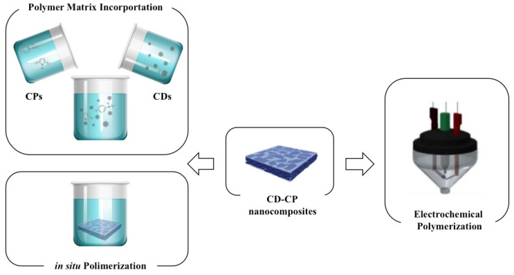
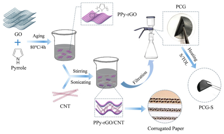
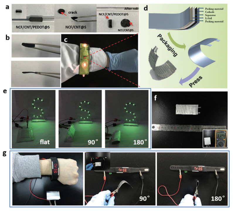
Carbon nanomaterials are at the forefront of the newest technologies of the third millennium, and together with conductive polymers, represent a vast area of indispensable knowledge for developing the devices of tomorrow. This review focusses on the most recent advances in the field of conductive nanotechnology, which combines the properties of carbon nanomaterials with conjugated polymers. Hybrid materials resulting from the embedding of carbon nanotubes, carbon dots and graphene derivatives are taken into consideration and fully explored, with discussion of the most recent literature. An introduction into the three most widely used conductive polymers and a final section about the most recent biological results obtained using carbon nanotube hybrids will complete this overview of these innovative and beyond belief materials.

Keywords: carbon dots; carbon nanotubes; conjugated polymers; graphene; poly(3,4-ethylenedioxythiophene), polypyrrole; polyaniline.


Conflict of interest statement

The authors declare no conflict of interest.

Figures

Figure 6
Figure 6
(a) Schematic diagram of the synthesis procedure of CDs@Mat-PANI. Adapted from reference [110] (b) Response current curves of PPy/TiO2 and CQDs–PPy/TiO2 nanotube hybrid in a regular pulse voltammetry deposition process. (c) Illustration of the Auto-Pret system coupled with electrochemical detection for online modification of the screen-printed carbon electrode (SPCE) with polyaniline (PANI)-GQD and the determination of Cr. Adapted with permission from ref. [116,117]. Copyright Royal Society of Chemistry (2015) and Elsevier (2016), respectively.
Figure 7
Figure 7
SEM images of (a) PPy@Cdots (1:1) and (b) PANI@Cdots (1:0.4) supercapacitor. (c) Emission spectra of Cdot-PPy composite. (d) UV–Vis absorption spectra of CD-PPy composite in water. (e) Nyquist plots and the equivalent circuit, (f) Nyquist plots of the supercapacitor based on CQDs-PANI/CP(LI) and the corresponding equivalent circuit. Reprinted with permission from reference [37,112,119,128]. Copyright Elsevier (2015, 2017) and American Chemical Society (2016, 2018).
Figure 1
Figure 1
Skeletal formulas of polyaniline in different oxidation states and their resonance, (a) leucoemeraldine, (b) Oxidative chemical polymerization.
Figure 2
Figure 2
Pyrrole polymerization reaction, further redox equilibria and their resonance.
Figure 3
Figure 3
(3,4-ethylenedioxythiophene) (EDOT) polymerization reaction in presence of poly(styrenesulfonate) (PSS).
Figure 4
Figure 4
Illustration of the types of CDs considered. Carbon quantum dots (CQDs), graphene quantum dots (GQDs) and carbon nanodots (CNDs).
Figure 5
Figure 5
General scheme of the fabrication and processing methods of carbon dot–conductive polymer (CD–CP) nanocomposites.
Figure 8
Figure 8
Applications where CD–CP composites have been applied. Adapted with permission from references [37,112,114,116], Copyright Elsevier (2015) and American Chemical Society (2013, 2016) and The Royal Society of Chemistry (2015).
Figure 9
Figure 9
Scheme of in situ polymerization of nanorod-PANI-graphene developed by Hu et al. Reproduced with permission from reference [11]. Copyright (2012) The Royal Society of Chemistry.
Figure 10
Figure 10
Scheme of the common solvent mixing procedure for the fabrication of graphene/CP composites.
Figure 11
Figure 11
Illustration of GO/PPy-DEX nanocomposite (a) and its DEX release (b) after electrical stimulation. (c) Cumulative release of the nanocomposite for up 400 pulses, without electrical stimulation no drug release was observed. Adapted from reference [184].
Figure 12
Figure 12
Representation of the cotton fabrics of PEDOT:PSS/G with strain response. Reprinted with permission from reference [183], Copyright Elsevier (2017).
Figure 13
Figure 13
(a) Schematic illustration for the synthesis of the core-shell 3D structured PPy/MnO2-rGO-CNTs composite. (b) SEM and (c) TEM image of the PPy/MnO2-rGO-CNTs composite. CNT: carbon nanotubes. Adapted with permission from reference [237], Copyright (2017) Elsevier.
Figure 14
Figure 14
Schematic diagram of the synthesis process and structure of PCG-S paper. Reprinted with permission from reference [38]. Copyright (2020) American Chemical Society.
Figure 15
Figure 15
(a) In vitro cytotoxicity assay of C8-D1A astrocytes cultivated for 48 h on scaffolds in the presence or absence of CNTs. Absorbance readings for each scaffold are plotted as an average of five independent experiments (n = 4 ± SD). Confocal images after (b) calcein-AM stain of viable cells (green) and (c) the F-actin cytoskeleton (yellow) staining of PPy/CNT scaffolds after 2 days of culture. From left to right: stained cells (green or yellow), scaffold (gray), and merge. Images are split views of Z-stacks maximum intensity projections (57 μm optical sections). The elongated morphology of the cells indicates a good biocompatibility of the material. Scale bar = 50 μm. Reprinted with permission from reference [199]. Copyright (2018) American Chemical Society.
Figure 16
Figure 16
(a) Temperature–time profiles of LED modules incorporating Al, pure PDMS, and 3D-PDMS composites as heat sinks. (b) Photograph of the 3D-PDMS composite and (c) LED modulus. (d) Cross sectional image of an LED modulus featuring a polymeric heat sink. (ep) Thermal imaging photographs of LED modules featuring (ej) pure PDMS and (kp) 3D-MWCNT/PDMS composite (10.0 wt%) as heat sinks, taken after various heating times. Reprinted with permission from reference [250]. Copyright (2008) Elsevier.
Figure 17
Figure 17
Applications of flexible batteries in charging LEDs, a flexible bracelet, and a smart watch. (a) Photographs of the freestanding NCF/CNT/PEDOT@S and NCF/CNT@S electrodes curled around a glass rod. (b) Photographs of the freestanding NCF/CNT/PEDOT@S electrodes before (top) and after (below) pressing. (c) Powering a flexible bracelet. (d) Schematic of the structure of the flexible battery. (e) Photographs of the soft-package Li–S battery lighting up 11 LEDs. (f) Size of the flexible battery for a bracelet (inset: initial voltage output of the flexible battery). (g) Powering a smart bracelet with the flexible NCF/CNT/PEDOT@S battery at 90° and 180° (inset: flat state). Reprinted with permission from reference [241]. Copyright (2018) RSC Pub.

References

    1. Letheby H. On the production of a blue substance by the electrolysis of sulphate of aniline. J. Chem. Soc. 1862;15:161–163. doi: 10.1039/JS8621500161. - DOI
    1. De Surville R., Jozefowicz M., Yu L.T., Pepichon J., Buvet R. Electrochemical chains using protolytic organic semiconductors. Electrochim. Acta. 1968;13:1451–1458. doi: 10.1016/0013-4686(68)80071-4. - DOI
    1. Diaz A.F., Logan J.A. Electroactive polyaniline films. J. Electroanal. Chem. Interfacial Electrochem. 1980;111:111–114. doi: 10.1016/S0022-0728(80)80081-7. - DOI
    1. MacDiarmid A.G., Epstein A.J. Polyanilines: A novel class of conducting polymers. Faraday Discuss. Chem. Soc. 1989;88:317. doi: 10.1039/dc9898800317. - DOI
    1. Macdiarmid A.G., Chiang J.C., Richter A.F., Epstein A.J. Polyaniline: A new concept in conducting polymers. Synth. Met. 1987;18:285–290. doi: 10.1016/0379-6779(87)90893-9. - DOI

LinkOut - more resources