. 2021 Mar 6;21(1):100.
doi: 10.1186/s12903-021-01448-9.

Standardization of three-dimensional pose of cylindrical implants from intraoral radiographs: a preliminary study

Affiliations

Standardization of three-dimensional pose of cylindrical implants from intraoral radiographs: a preliminary study

Saverio Cosola et al. BMC Oral Health. .

Abstract

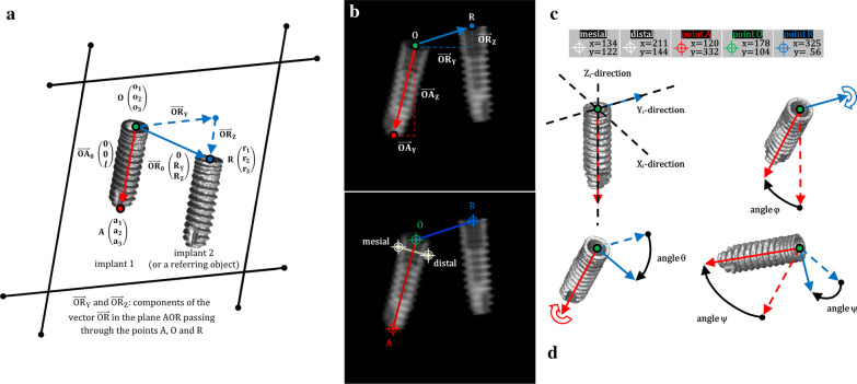
Background: To introduce a theoretical solution to a posteriori describe the pose of a cylindrical dental fixture as appearing on radiographs; to experimentally validate the method described.

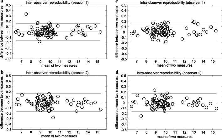
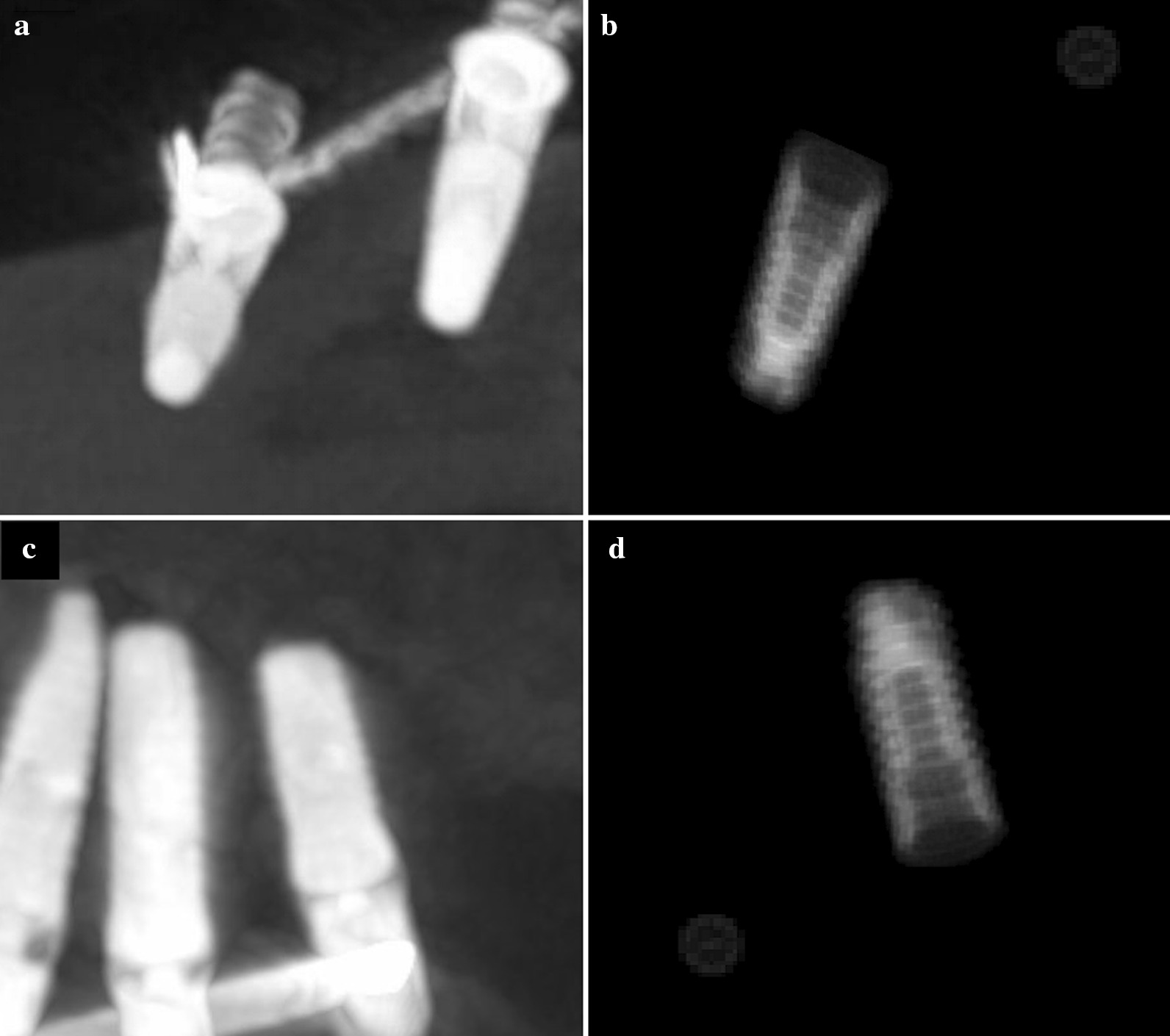
Methods: The pose of a conventional dental implant was described by a triplet of angles (phi-pitch, theta-roll, and psi-yaw) which was calculated throughout vector analysis. Radiographic- and simulated-image obtained with an algorithm were compared to test effectiveness, reproducibility, and accuracy of the method. The length of the dental implant as appearing on the simulated image was calculated by the trigonometric function and then compared with real length as it appeared on a two-dimensional radiograph.

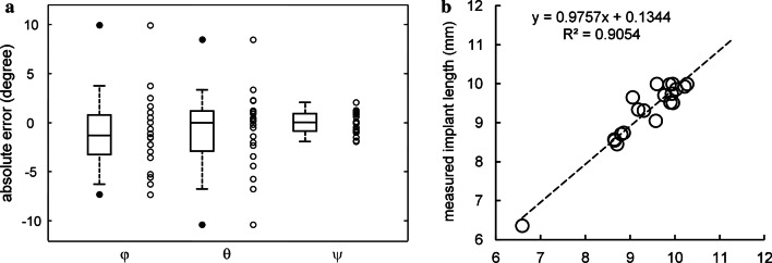
Results: Twenty radiographs were analyzed for the present in silico and retrospective study. Among 40 fittings, 37 resulted as resolved with residuals ≤ 1 mm. Similar results were obtained for radiographic and simulated implants with absolute errors of - 1.1° ± 3.9° for phi; - 0.9° ± 4.1° for theta; 0° ± 1.1° for psi. The real and simulated length of the implants appeared to be heavily correlated. Linear dependence was verified by the results of the robust linear regression: 0.9757 (slope), + 0.1344 mm (intercept), and an adjusted coefficient of determination of 0.9054.

Conclusions: The method allowed clinicians to calculate, a posteriori, a single real triplet of angles (phi, theta, psi) by analyzing a two-dimensional radiograph and to identify cases where standardization of repeated intraoral radiographies was not achieved. The a posteriori standardization of two-dimensional radiographs could allowed the clinicians to minimize the patient's exposure to ionizing radiations for the measurement of marginal bone levels around dental implants.

Keywords: Computer simulation; Dental implant(s); Dental informatics/bioinformatic; Digital imaging/radiology; Mathematical modeling.


Conflict of interest statement

The authors declare that they have no competing interest.

Figures

Fig. 1
Fig. 1
a Line from the neck of the cylindrical implant to the apex, and symmetrical from left to right, is the direction OA; the direction OA touches the centre of the implant shoulder in the implant reference point, i.e., the point O. Line from the point O to the external reference point, i.e., the point R, is the direction OR; in present example the point R is the centre of the implant shoulder of a further dental implant. OA0 = (0 0 l) were the lengthwise starting vector (red arrow), where l is the implant length, and RY and RZ are the components of the crosswise vector (blue arrow), OR0 = (0 RY RZ), along plane AOR, represented by the trapezoid indicated by the thin black lines, and passing through point A = (a1, a2, a3), O = (o1, o2, o3) and R = (r1, r2, r3). b Drawing of the two vectors, OA and OR on mega pixel simulated two-dimensional image of a dental implant with measured reference points on another implant: mesial point, distal point, point A, point O and point R with (c) the list of variables and that of their values as obtained from the free standalone software Osiris 4.19 which was used to acquire the two-dimensional coordinates of the points. d Three-dimensional renderings of the cylindrical implant using the three consecutive rotational angles φ, θ and ψ along the three direction of the main implant axes Xi, Yi and Zi
Fig. 2
Fig. 2
a, b Inter-onserver and c, d Intra-observer reproducibility (Bland–Altman plots) of the measured lengths in millimeters of the two vectors OA and OR. The straight horizontal line represents the mean difference between sessions and the dashed horizontal lines represent the limits of agreement (95% confidence interval)
Fig. 3
Fig. 3
Radiographs of lower and upper arch dental implants (on the right: a, c) and related virtual phantom with respective referring points (on the left: b, d)
Fig. 4
Fig. 4
a Accuracy was measured as the difference between two sets of angles (three angles of rotations) obtained comparing cylindrical implants on real radiographs versus phantom projection on virtual radiographs. Data were represented as scatter (empty points) and box-and-whisker plot (the box line represents the lower. median. and upper quartile values; the whisker lines include the rest of the data). Outliers (solid points) were data with values beyond the ends of the whiskers. b Linear dependence between registered length of the implant as it appears in the radiograph and length as obtained by means of the angular correction factor (CF). The dashed line represents the robust fit (equation and adjusted coefficient of determination are indicated in the graph)

References

    1. Cassetta M, Di Giorgio R, Barbato E. Are intraoral radiographs reliable in determining peri-implant marginal bone level changes? The correlation between open surgical measurements and peri-apical radiographs. Int J Oral Maxillofac Surg. 2018;47(10):1358–1364. doi: 10.1016/j.ijom.2018.05.018. - DOI - PubMed
    1. Meijer HJ, Steen WH, Bosman F. Standardized radiographs of the alveolar crest around implants in the mandible. J Prosthet Dent. 1992;68:318–321. doi: 10.1016/0022-3913(92)90337-a. - DOI - PubMed
    1. Menchini-Fabris GB, Covani U, Toti P, Marconcini S, Barone A, Martuscelli R. A methodological approach to standardize and control the quality of the position and alignment of lamina implants on two-dimensional radiographs. Oral Radiol. 2020;36:288–306. doi: 10.1007/s11282-019-00374-5. - DOI - PubMed
    1. Hoffmann KR, Esthappan J. Determination of three-dimensional positions of known sparse objects from a single projection. Med Phys. 1997;24:555–564. doi: 10.1118/1.597938. - DOI - PubMed
    1. Schulze R, Bruellmann DD, Roeder F, d'Hoedt B. Determination of projection geometry from quantitative assessment of the distortion of spherical references in single-view projection radiography. Med Phys. 2004;31:2849–2854. doi: 10.1118/1.1796951. - DOI - PubMed

Substances

LinkOut - more resources