

Implementation of a fully implantable middle-ear hearing device chip
- PMID: 33682777
- PMCID: PMC8150658
- DOI: 10.3233/THC-218038
Implementation of a fully implantable middle-ear hearing device chip
Abstract
Background and objective: Recently, with the increase in the population of hearing impaired people, various types of hearing aids have been rapidly developed. In particular, a fully implantable middle ear hearing device (F-IMEHD) is developed for people with sensorineural hearing loss. The F-IMEHD system comprises an implantable microphone, a transducer, and a signal processor. The signal processor should have a small size and consume less power for implantation in a human body.
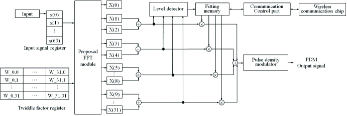
Methods: In this study, we designed and fabricated a signal-processing chip using the modified FFT algorithm. This algorithm was developed focusing on eliminating time delay and system complexity in the transform process. The designed signal-processing chip comprises a 4-channel WDRC, a fitting memory, a communication 1control part, and a pulse density modulator. Each channel is separated using a 64-point fast Fourier transform (FFT) method and the gain value is matched using the fitting table in the fitting memory.
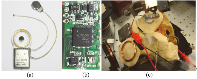
Results and conclusion: The chip was designed by Verilog-HDL and the designed HDL codes were verified by Modelsim-PE 10.3 (Mentor graphics, USA). The chip was fabricated using a 0.18 μm CMOS process (SMIC, China). Experiments were performed on a cadaver to verify the performance of the fabricated chip.
Keywords: CMOS process; Cadaver experiment; Fully implantable middle ear hearing device; Verilog-HDL; wide dynamic range.
Conflict of interest statement
The authors declare that there is no conflict of interest regarding the publication of this paper.
Figures


Similar articles
-
Implementation of integrated circuit and design of SAR ADC for fully implantable hearing aids.Technol Health Care. 2017 Jul 20;25(S1):83-92. doi: 10.3233/THC-171309. Technol Health Care. 2017. PMID: 28582895
-
A 1-channel 3-band wide dynamic range compression chip for vibration transducer of implantable hearing aids.Biomed Mater Eng. 2014;24(1):1009-17. doi: 10.3233/BME-130898. Biomed Mater Eng. 2014. PMID: 24211991
-
Concept and Evaluation of a New Piezoelectric Transducer for an Implantable Middle Ear Hearing Device.Sensors (Basel). 2017 Nov 2;17(11):2515. doi: 10.3390/s17112515. Sensors (Basel). 2017. PMID: 29099047 Free PMC article.
-
[Active electronic hearing implants for middle and inner ear hearing loss--a new era in ear surgery. II: Current state of developments].HNO. 1997 Oct;45(10):758-68. doi: 10.1007/s001060050154. HNO. 1997. PMID: 9445848 Review. German.
-
[Active electronic cochlear implants for middle and inner ear hearing loss--a new era in ear surgery. I: Basic principles and recommendations on nomenclature].HNO. 1997 Oct;45(10):749-57. doi: 10.1007/s001060050153. HNO. 1997. PMID: 9445847 Review. German.
References
-
- Dillon H. Hearing Aids. Sydney: Boomerang Press; 2001.
-
- Pollack MC, Carhart R. Amplification for the Hearing Impaired. Orlando: Grune & Stratton Incorporation; 1988.
-
- Kates JM. Digital Hearing Aids. San Diego: Plural Publishing Incorporation; 2008.
-
- Kochkin S. MarkeTrak VIII: Consumer satisfaction with hearing aids is slowly increasing. Hearing Journal. 2010; 63(1): 19-32.
-
- Goode R, Rosenbaum M, Maniglia A. The history and development of the implantable hearing aid. The Otolaryngologic Clinics of North America. 1995; 28(1): 1-16. - PubMed
MeSH terms
LinkOut - more resources
Full Text Sources
Other Literature Sources
