. 2021 Mar 12;12(1):1633.
doi: 10.1038/s41467-021-21920-y.

Digital logic gates in soft, conductive mechanical metamaterials

Affiliations

Digital logic gates in soft, conductive mechanical metamaterials

Charles El Helou et al. Nat Commun. .

Abstract

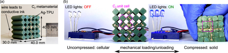
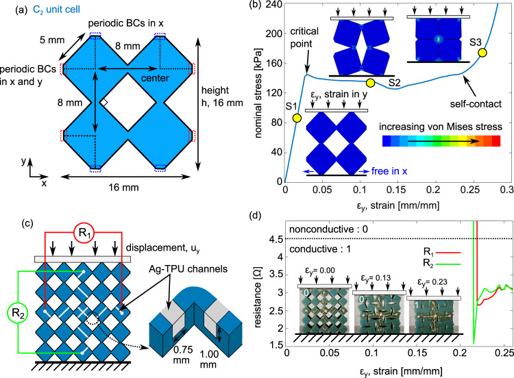
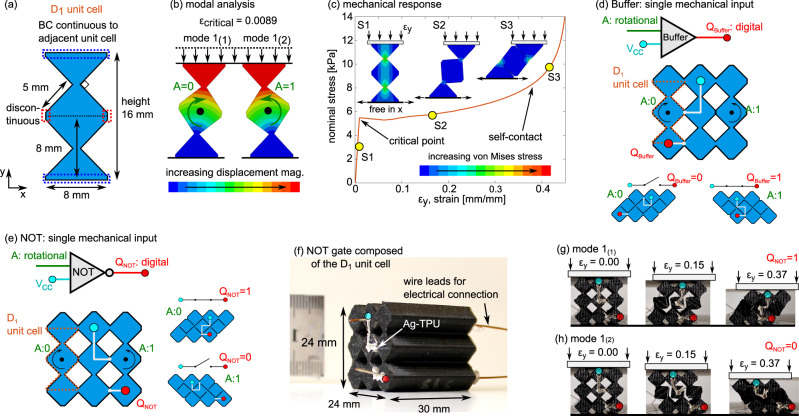
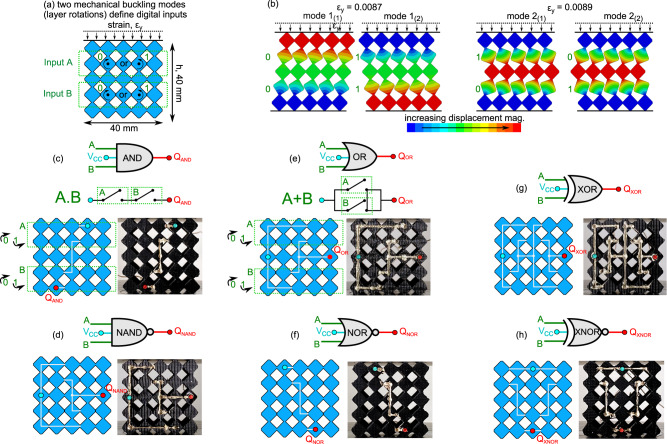
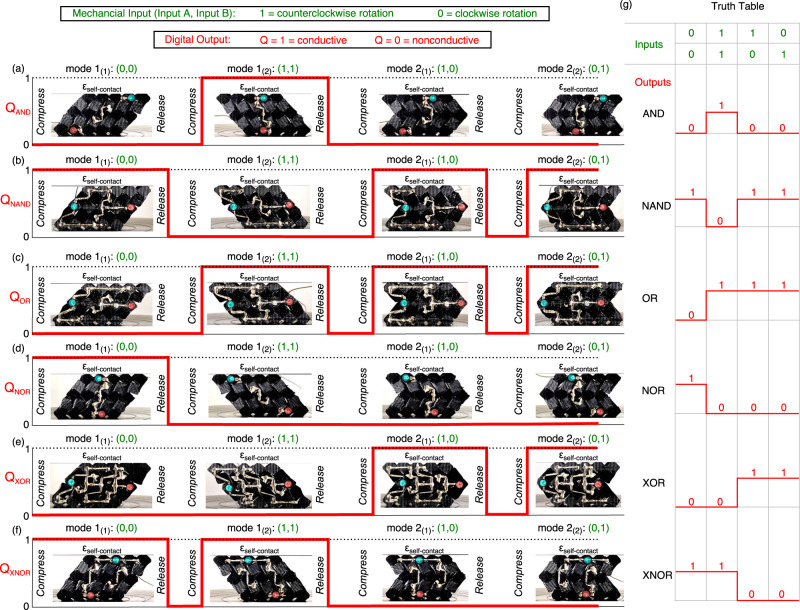
Integrated circuits utilize networked logic gates to compute Boolean logic operations that are the foundation of modern computation and electronics. With the emergence of flexible electronic materials and devices, an opportunity exists to formulate digital logic from compliant, conductive materials. Here, we introduce a general method of leveraging cellular, mechanical metamaterials composed of conductive polymers to realize all digital logic gates and gate assemblies. We establish a method for applying conductive polymer networks to metamaterial constituents and correlate mechanical buckling modes with network connectivity. With this foundation, each of the conventional logic gates is realized in an equivalent mechanical metamaterial, leading to soft, conductive matter that thinks about applied mechanical stress. These findings may advance the growing fields of soft robotics and smart mechanical matter, and may be leveraged across length scales and physics.


Conflict of interest statement

The authors declare no competing interests.

Figures

Fig. 1
Fig. 1. Compaction principle of electrical network switching in soft, conductive mechanical metamaterials.
a Introduction of a metamaterial composed of C2 unit cell with conductive Ag-TPU trace. b C2 metamaterial in series with a power source and LED array to illustrate switching functionality. Uncompressed: Open circuit, LED off. Compacted: Closed circuit, LED on.
Fig. 2
Fig. 2. Bit abstraction via open/closed circuit.
a C2 unit cell dimensions with periodic boundary conditions. b Simulated mechanical response of C2 unit cell featuring three regimes of general behavior and shape change. c Schematic of C2 metamaterial with Ag-TPU biaxial switch network. Resistance measurements R1  and R2 are monitored across two terminal pairs. d Experimental resistance measurement with photos depicting the deformations in the three compression regimes.
Fig. 3
Fig. 3. Bit abstraction via buckling direction.
a D1 unit cell dimensions with boundary conditions. b Modal analysis of D1 unit cell with two deformation states, mode 1(1) and mode 1(2). c Simulated mechanical response of D1 unit cell featuring three deformation regimes. d Schematic of Buffer gate as direct electrical switch governed by a single mechanical rotation input, corresponding to the buckling mode. e Schematic and (f) experimental image of the NOT gate with one mechanical input rotation (green) and one digital output terminal (red) QNOT on the metamaterial composed of D1 unit cells. The powered input terminal is the cyan node, Vcc. Photos of the NOT gate under uniaxial compression as it exhibits buckling (g) mode 1(1) and (h) mode 1(2), along with the corresponding digital outputs QNOT (red node).
Fig. 4
Fig. 4. Formulation of digital logic gates in soft, conductive mechanical metamaterials.
a Schematic of the D1 based metamaterials. Inputs A and B are the rotations in the first and second layers, respectively. b Modal analysis illustrating four possible deformation states. Schematics and experimental images of the Ag-TPU network on the metamaterials for (c) AND, (d) NAND, (e) OR, (f) NOR, (g) XOR, and (h) XNOR logic gates. AND and OR include corresponding switched circuit schematics. Each gate contains two mechanical inputs A and B (green) and one digital output Q (red). The powered input terminal is the cyan node, Vcc.
Fig. 5
Fig. 5. Processing all digital logic operations in soft, conductive mechanical metamaterials.
Logic gate digital output Boolean response at each of the four compact states for the (a) AND, (b) NAND, (c) OR, (d) NOR, (e) XOR, and (f) XNOR logic gate. The respective mechanical inputs (green) for each of the deformation states directly relate to (g) the logic gates truth table inputs.

References

    1. Harris KD, Elias AL, Chung H-J. Flexible electronics under strain: a review of mechanical characterization and durability enhancement strategies. J. Mater. Sci. 2016;51:2771–2805. doi: 10.1007/s10853-015-9643-3. - DOI
    1. Rogers JA, Someya T, Huang Y. Materials and mechanics for stretchable electronics. Science. 2010;327:1603–1607. doi: 10.1126/science.1182383. - DOI - PubMed
    1. Zhu J, Dexheimer M, Cheng H. Reconfigurable systems for multifunctional electronics. npj Flex. Electron. 2017;1:206–214. doi: 10.1038/s41528-017-0009-6. - DOI
    1. Nassar JM, Rojas JP, Hussain AM, Hussain MM. From stretchable to reconfigurable inorganic electronics. Extrem. Mech. Lett. 2016;9:245–268. doi: 10.1016/j.eml.2016.04.011. - DOI
    1. Huang S, Liu Y, Zhao Y, Ren Z, Guo CF. Flexible electronics: stretchable electrodes and their future. Adv. Funct. Mater. 2019;29:1805924. doi: 10.1002/adfm.201805924. - DOI

Publication types