. 2021 Jun:233:117952.
doi: 10.1016/j.neuroimage.2021.117952. Epub 2021 Mar 11.

Scattered Light Imaging: Resolving the substructure of nerve fiber crossings in whole brain sections with micrometer resolution

Affiliations

Scattered Light Imaging: Resolving the substructure of nerve fiber crossings in whole brain sections with micrometer resolution

Miriam Menzel et al. Neuroimage. 2021 Jun.

Abstract

For developing a detailed network model of the brain based on image reconstructions, it is necessary to spatially resolve crossing nerve fibers. The accuracy hereby depends on many factors, including the spatial resolution of the imaging technique. 3D Polarized Light Imaging (3D-PLI) allows the three-dimensional reconstruction of nerve fiber tracts in whole brain sections with micrometer in-plane resolution, but leaves uncertainties in pixels containing crossing fibers. Here we introduce Scattered Light Imaging (SLI) to resolve the substructure of nerve fiber crossings. The measurement is performed on the same unstained histological brain sections as in 3D-PLI. By illuminating the brain sections from different angles and measuring the transmitted (scattered) light under normal incidence, light intensity profiles are obtained that are characteristic for the underlying brain tissue structure. We have developed a fully automated evaluation of the intensity profiles, allowing the user to extract various characteristics, like the individual directions of in-plane crossing nerve fibers, for each image pixel at once. We validate the reconstructed nerve fiber directions against results from previous simulation studies, scatterometry measurements, and fiber directions obtained from 3D-PLI. We demonstrate in different brain samples (human optic tracts, vervet monkey brain, rat brain) that the 2D fiber directions can be reliably reconstructed for up to three crossing nerve fiber bundles in each image pixel with an in-plane resolution of up to 6.5 μm. We show that SLI also yields reliable fiber directions in brain regions with low 3D-PLI signals coming from regions with a low density of myelinated nerve fibers or out-of-plane fibers. This makes Scattered Light Imaging a promising new imaging technique, providing crucial information about the organization of crossing nerve fibers in the brain.

Keywords: Brain structure; Connectivity; Light scattering; Nerve fiber crossings; White matter.


Figures

None
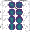
Graphical abstract
Fig. 1
Fig. 1
Schematic drawing of the setup used for Scattered Light Imaging (SLI). (a) Side view of the setup consisting of an LED panel (with diffuser plate), a specimen stage with sample, a sheltering tube, and a CCD camera. A mask with a hole is placed on top of the LED panel so that the sample is illuminated under a large polar angle θ. (b) Top view of the two masks used for the SLI measurements (Left: circular holes, Right: rectangular holes).
Fig. 2
Fig. 2
Evaluation of SLI profiles. (a) Image series obtained from an SLI measurement of a coronal vervet brain section (upper left corner, see Table F1 #90). The measurement was performed using the mask with rectangular holes and 15-steps. The green arrowheads at the image borders indicate the illumination angle ϕ. (b) Left: Schematic drawing of the nerve fiber geometries associated with the evaluated brain regions (in-plane, inclined, steep, and in-plane crossing fibers). The angle φ denotes the fiber direction in the xy-plane, the angle α the out-of-plane inclination. Right: Corresponding SLI profiles obtained from a region of 10×10 pixels, indicated by the red arrows in (a). The prominence of the peaks (in red) is computed by the vertical distance between the top of the peak and the higher of the two neighboring minima, min1 and min2 (minimum values between the peak and the next higher points on the left and right side of the peak). Only peaks with a prominence 8% are considered for evaluation (the fifth peak in (iv) is assumed to be a noise artifact). The peak width (dark blue) is determined as the full width of the peak at a height corresponding to the peak height minus half of the peak prominence. The dashed vertical lines indicate the corrected positions of the determined peaks, the solid vertical lines the computed fiber direction angles φ. (For interpretation of the references to color in this figure legend, the reader is referred to the web version of this article.)
Fig. 3
Fig. 3
Comparison of SLI and scatterometry profiles. (a) Average transmitted light intensity of the SLI measurement for two and three crossing sections of human optic tracts (see Table F1 #162,181,186). (b) Normalized SLI profiles (orange) and scatterometry profiles (blue) obtained from the tissue spots indicated in (a). The vertical lines show the determined peak positions. (c) Difference in the number of detected peaks (top) and in the detected peak positions (bottom) between the SLI and scatterometry profiles for 200 evaluated brain tissue spots (see non-white circles in Fig. C1). (For interpretation of the references to color in this figure legend, the reader is referred to the web version of this article.)
Fig. 4
Fig. 4
Parameter maps from a 3D-PLI and an SLI measurement of two crossing sections of human optic tracts (section 36, Table F1 #158). For better distinction, the crossing sections are delineated by contour lines. (a) Normalized transmittance images for the whole section of the human optic chiasm (on the left) and for the crossing sections of optic tracts (on the right). The chiasm section was divided along the dashed line into two parts, and the sections of optic tracts were placed on top of each other (B on top of A). (on = optic nerve, ot = optic tract, SON = supraoptic nucleus, sod = supraoptic decussation). (b) Retardation image of the crossing sections of optic tracts. (c) Average intensity of the (non-normalized) SLI profiles. (d) Number of peaks in the SLI profiles (left: all peaks with prominence 0%; right: only peaks with prominence 8% of the total signal amplitude), shown in different colors. (e) Average peak prominence and average peak width (computed by averaging over all prominent peaks in an SLI profile). The minimum values are displayed in dark blue, the maximum values in yellow. (f) Distance between two prominent peaks in the SLI profiles (regions with more than two prominent peaks are shown in white). (g) Fiber direction angles (φ1,φ2) computed from the arithmetic mean value of the peak pair positions for regions with two or four prominent peaks in the SLI profiles. Regions with two prominent peaks (interpreted as non-crossing fibers) are shown in both images, φ1 and φ2. The image on the right shows the 2D fiber directions as blue and green lines sampled from every 24th image pixel. (For interpretation of the references to color in this figure legend, the reader is referred to the web version of this article.)
Fig. 5
Fig. 5
Reconstructed nerve fiber directions from 3D-PLI and SLI measurements for two and three crossing sections of human optic tracts. (a–b) In-plane fiber direction angles obtained from a 3D-PLI measurement and an SLI measurement of two crossing sections of optic tracts (section 36, Table F1 #158). The fiber direction is encoded by hue according to the color legend in (ii). The left images (i) show the color-coded fiber directions of each image pixel. For image pixels in which the SLI measurement yields different fiber direction angles, only a single fiber direction angle is displayed. The middle images (ii) show the fiber directions as bars (a) for every 150th image pixel, and (b) for every 30th image pixel, using the same color code. The SLI fiber directions were replaced by the median fiber directions of each 3×3 pixels beforehand. (In this way, pixels for which the SLI measurement yields no fiber direction are replaced by the main fiber direction of the neighboring pixels. By taking the median and not the average, we ensure that the fiber directions are not distorted by averaging over the different fiber directions in the two bundles.) The right images (iii) show a zoom-in of (i) for a small region marked by the arrow, respectively. The corresponding transmittance and retardation images of the 3D-PLI measurement are shown in Fig. 4(a),(b). (c) In-plane fiber direction angles obtained from an SLI measurement of three crossing sections of optic tracts (sections 32/33, Table #186). The left image shows the color-coded fiber directions of each image pixel, the right image shows the fiber direction as colored bars for every 40th pixel (after computing the median of 3×3 pixels). For better reference, the sections of optic tracts are delineated by white contour lines and labeled by 1,2,3.
Fig. 6
Fig. 6
Comparison of SLI and 3D-PLI measurements for a coronal rat brain section (Table F1 #78): (a–b) Transmittance and retardation images obtained from a 3D-PLI measurement, registered onto the SLI image stack. Anatomical regions are labeled for better reference (cg = cingulum, cc = corpus callosum, fi = fimbria, df = dorsal fornix, ot = optic tract, sm = stria medullaris). (c) Difference between in-plane fiber direction angles obtained from 3D-PLI and SLI (evaluated in regions with one or two prominent peaks with prominence 8%). (d) Distance between the peaks. (e) 2D histogram of all image pixels in (c) showing the difference between the in-plane fiber direction angles (SLI – PLI) plotted against the retardation. Minimum values (zero) are shown in dark blue, maximum values in yellow (log-scale). The red curve in the 2D histogram shows the cumulated values (summed over all retardation values) for 256 bins between ±90. The graph below shows the standard deviation σ of the angle difference plotted against the retardation (with a binning of 0.1). (f) Zoomed-in region of the stria medullaris. The histogram shows the fiber direction angles in the delineated region evaluated for SLI (blue) and 3D-PLI (red). (g) 2D histogram and standard deviation of the peak distances in (d) plotted against the retardation. The black curve in the 2D histogram shows peak distances of simulated line profiles for different out-of-plane fiber inclination angles (retardation values) obtained from Fig. 7(d). (h) Zoomed-in region of the retardation image (optic tract). Values with a retardation 0.5 and a peak distance 160 (red rectangle in (g)) are marked in red. The graph shows the SLI profile evaluated in a region of 10×10 pixels (yellow asterisk, supraoptic decussation (sod) with retardation 0.4). (For interpretation of the references to color in this figure legend, the reader is referred to the web version of this article.)
Fig. 7
Fig. 7
Transition between in-plane and out-of-plane fibers. (a) Coronal and sagittal section of a vervet brain (Table F1 #161 and #139). The images show the transmitted light intensity in the SLI measurement for an illumination from 12 o’clock (ϕ=0). The approximate location of the coronal (sagittal) section plane is marked in the other section plane by a blue (red) line. The zoomed-in areas show the transition between the corpus callosum (cc) and the cingulum (cg). (b) Cranio-caudal course of averaged SLI profiles for a chain of neighboring regions with 3×3 image pixels, evaluated along the rainbow-colored lines in the zoomed-in areas in (a). (c) Left: Artificial fiber bundle with out-of-plane inclination angle α. Right: simulated scattering pattern for α=50. The images were adapted from Menzel et al. (2020a), fig. 7(a), licensed with CC BY 4.0. (d) Simulated line profiles for different inclination angles α. The line profiles were computed from the simulated (blurred) scattering patterns as described in Section 2.7 (average intensities evaluated along the white dashed circle in (c)). (For interpretation of the references to color in this figure legend, the reader is referred to the web version of this article.)
Fig. 8
Fig. 8
Reconstructed nerve fiber directions of coronal vervet brain sections (Table F1 #90 and #161): (a) Left: SLI image (ϕ=0) of vervet brain section no. 512. Right: retardation image obtained from a 3D-PLI measurement of the same section. (b) In-plane fiber directions obtained from the 3D-PLI measurement (px = 1.33 µm). (c) Fiber directions obtained from the SLI measurement (px = 13.7 μm). (d) SLI image (ϕ=0) of vervet brain section no. 493 (px = 6.5 μm). (e) Fiber directions obtained from the SLI measurement of the sample. The fiber directions are encoded in different colors (according to the color legend in (f)). The colored images show the fiber directions for each image pixel. The vector maps show the fiber direction for every 40th image pixel (b,c) and for every 50th image pixel (e). The SLI fiber directions were replaced by the median fiber direction of every 3×3 pixels beforehand. For better reference, the retardation image is shown in the background of the vector maps, respectively. The yellow rectangles mark the region of the corona radiata shown in the zoomed-in areas. (f) Sketch of crossing fiber pathways in the corona radiata, known from vervet brain atlases (Woods et al. (2011)). The start/end points of the pathways are labeled by numbers (also shown in the zoomed-in areas of the vector maps). (For interpretation of the references to color in this figure legend, the reader is referred to the web version of this article.)
Fig. A1
Fig. A1
Determination of the optimum prominence value for peak detection. (a) Average transmitted light intensity in an SLI measurement of two and three crossing sections of optic tracts ((i)-(iii)) and a coronal vervet brain section (iv). Regions used for evaluation are surrounded by colored lines: in-plane parallel fibers (green), two crossing fiber bundles/layers (magenta), three crossing fiber bundles/layers (yellow), and out-of-plane fibers (blue). cg = cingulum; f = fornix. (b) Fraction of correctly determined regions plotted against the minimum prominence value used for peak detection evaluated for the different types of regions shown in (a). The black curve shows the average of all curves. (For interpretation of the references to color in this figure legend, the reader is referred to the web version of this article.)
Fig. B1
Fig. B1
Correction of determined peak positions in the SLI profiles. (a) The orange curve shows the smoothed line profile (scatterometry profile) for three crossing sections of optic tracts (the measured region is marked in Fig. C1 by a yellow arrow). The blue curve shows the line profile sampled in steps of 15 (starting at ϕ=0). Because of the sampling, the determined peak positions ϕ^uncorr (vertical blue dashed lines) do not exactly correspond to the original peak positions ϕ^ in the smoothed line profile (vertical orange dashed lines). (b) The determined peak positions ϕ^uncorr (blue circles) were modified with different correction methods, yielding corrected peak positions ϕ^corr (colored arrows): Centroid over ±2 steps (orange), centroid between two minima (pink), centroid of peak tip (green) for a height of 5% of the total amplitude. (c) The histograms show the difference between the original peak positions in the smoothed line profiles (ϕ^) and the corrected peak positions in the sampled line profiles (ϕ^corr) for the different methods. In total, 15×232 sampled line profiles were compared to 232 smoothed line profiles (scatterometry profiles) of 9 different samples (see all circles in Fig. C1). (d) Absolute mean and standard deviation of the histogram (ϕ^ϕ^corr), where the peak positions were corrected by computing the centroid of the peak tips at different heights ({0%,1%,,20%} of the total signal amplitude). For 6%, the standard deviation becomes minimal (2.4). (For interpretation of the references to color in this figure legend, the reader is referred to the web version of this article.)
Fig. C1
Fig. C1
Comparison of SLI and scatterometry profiles for different brain tissue samples (coronal/sagittal vervet brain sections, two/three crossing sections of human optic tracts). (a) Average transmitted light intensity of the SLI measurements, labeled by the sample, section number, and measurement ID#. Table contains more details about the measurement, like the rotation angle by which the SLI images were rotated with respect to the scatterometry measurement. The circles indicate the positions of the tissue spots (with 1.12 mm diameter) that were measured by scatterometry. In the vervet brain sections, anatomical regions are labeled (cr = corona radiata; cg = cingulum; cc = corpus callosum; f = fornix). (b) Normalized SLI profiles (orange) and scatterometry profiles (blue) obtained from the tissue spots indicated by the green and magenta arrow in (a). The numbers at the top show the sum of distances between SLI and scatterometry profiles. The vertical orange/blue lines indicate the determined peak positions, the dashed-dotted lines the peaks that were not used for comparison. (c) Sum of distances between SLI and scatterometry profiles evaluated for 200 tissue spots (non-white circles in (a)): best 10% with smallest distance (green), best 10–25% (blue), worst 25-10% (orange), worst 10% (magenta). (For interpretation of the references to color in this figure legend, the reader is referred to the web version of this article.)
Fig. D1
Fig. D1
SLI profiles for two and three crossing sections of human optic tracts evaluated in regions with parallel and crossing nerve fibers. (a) Sections of the human optic chiasm were divided into two parts (marked by green and magenta contour lines, A and B) and the sections of the optic tracts (ot) were placed on top of each other under different crossing angles (see (c)). (on = optic nerve) (b) Scattered light intensity during an SLI measurement for a direction of illumination of ϕ=0 and 90. The green arrowheads at the image borders indicate the illumination angle. The straight magenta and green lines indicate the orientations of the fiber tracts which become visible when being illuminated from the broadside. (c) Average transmitted light intensity of an SLI measurement for two and three crossing sections of optic tracts. For better reference, the different sections are delineated by colored contour lines. The black crosses indicate the positions of the evaluated regions, the straight colored lines the predominant orientations of the nerve fibers in the respective regions. (d) Raw SLI profiles I(ϕ) obtained from the regions shown in (c), averaged for regions of 10×10 pixels (solid curves) and for a representative single pixel in their centers (dashed curves). The graphs in (i) belong to regions with non-crossing nerve fibers in the single layer tissue of the optic tract, the graphs in (ii) to regions with crossing nerve fibers in the dual or triple layer overlap. The vertical dashed lines in green/magenta/yellow indicate the approximate positions of the peaks in the SLI profiles in (i) and (ii). The samples with two crossing sections of optic tracts were measured 5 months and the sample with three crossing sections 3 months after tissue embedding (see Table F1 #76,75,186). (For interpretation of the references to color in this figure legend, the reader is referred to the web version of this article.)
Fig. E1
Fig. E1
Time-dependent changes in scattering for two crossing sections of human optic tracts (sections 18 and 37, Table F1 #33,105). (a) Average transmitted light intensity of the SLI measurement 3 days after tissue embedding. Three regions with 5×5 pixels were selected for evaluation (marked by crosses). The different sections of the optic tracts were delineated by magenta/green contour lines for better reference. (SON = supraoptic nucleus, sod = supraoptic decussation) (b) Non-normalized SLI profiles I(ϕ) and normalized SLI profiles IN(ϕ) for the three selected regions, evaluated at different times after tissue embedding (3 days up to 5 months). (c) Brain areas for which the SLI profiles show four prominent peaks (interpreted as two crossing fiber bundles) are displayed in different colors, depending on the time elapsed after tissue embedding. Areas for which the SLI profiles show two prominent peaks (interpreted as in-plane parallel fibers) are shown in gray. (d) Intensity values of the average transmitted light intensity of the SLI measurement evaluated along the yellow line in (a) for measurements at eight different times after tissue embedding (3 days until 8 weeks). The vertical dashed lines indicate the borders of the crossing region. (For interpretation of the references to color in this figure legend, the reader is referred to the web version of this article.)
Fig. F1
Fig. F1
SLI measurement with15 and 5-steps for three crossing sections of human optic tracts (see Table F1 #143). (a) Average of the transmitted light intensity in the SLI measurement (5 months after embedding) localizing four selected regions of interest (10 × 10 pixels). (b) SLI profiles of the selected regions obtained from a measurement with 15-steps (black curves) and 5-steps (red curves). The red vertical lines indicate the peak positions of the red curves. The measurements were performed with the masks with rectangular holes described in Section 2.3. The peak positions obtained from the 15 measurement are very similar to those obtained from the 5 measurement. (For interpretation of the references to color in this figure legend, the reader is referred to the web version of this article.)
Fig. F2
Fig. F2
Average peak width and prominence of the coronal rat brain section (Table F1 #78). For peaks with a prominence 8% of the total signal amplitude, the peak width and prominence were computed from the normalized SLI profiles for each image pixel and averaged for each SLI profile. The 2D histograms show the average peak width and prominence plotted against the retardation for each image pixel. The graphs below show the standard deviation σ plotted against the retardation.
Fig. F3
Fig. F3
Simulated scattering patterns for90-crossing, inclined fiber bundles. X-shape crossing fiber bundles (oriented diagonally to the x/y-axis) and + -shape crossing fiber bundles (oriented along x and y) were rotated around the x-axis (as indicated by the red arrow) to obtain crossing fiber bundles with different inclination angles α. The middle images show the corresponding scattering patterns, the graphs at the left/right show the line profiles obtained after performing a Gaussian blur with 8 radius (cf. Section 2.7) and computing the radial sum of the scattering patterns. Scattering peaks are indicated by green/magenta lines. The simulations were performed as described in Menzel et al. (2020a), for 90-crossing interwoven fibers in a volume of 50×50×50 µm3. For the X-shaped crossing fibers (left), the scattering peaks in the lower half of the scattering pattern merge much faster than the scattering peaks in the upper half of the scattering pattern with increasing fiber inclination. The scattering pattern of the +-shaped crossing fibers (right) is a superposition of the scattering pattern of an in-plane parallel fiber bundle (x-bundle) and an inclined fiber bundle (y-bundle): While the peak positions of the x-bundle (magenta peaks) remain unchanged, the peaks of the y-bundle (green peaks) merge with increasing fiber inclination as expected for inclined fibers. The study shows that line profiles of strongly inclined crossing fibers look different from line profiles of in-plane crossing or parallel inclined fibers and might be used for distinction. (For interpretation of the references to color in this figure legend, the reader is referred to the web version of this article.)

Similar articles

Cited by

References

    1. Aboitiz F., Ide A., Olivares R. Corpus Callosum Morphology in Relation to Cerebral Asymmetries in the Postmortem Human. In: Zaidel E., Iacoboni M., editors. The Parallel Brain: The Cognitive Neuroscience of the Corpus Callosum. Massachusetts Institute of Technology; 2003. pp. 33–46.
    1. Avants B.B., Epstein C.L., Grossman M., Gee J.C. Symmetric diffeomorphic image registration with cross-correlation: evaluating automated labeling of elderly and neurodegenerative brain. Med. Image Anal. 2008;12(1):26–41. doi: 10.1016/j.media.2007.06.004. - DOI - PMC - PubMed
    1. Avants B.B., Tustison N.J., Song G., Cook P.A., Klein A., Gee J.C. A reproducible evaluation of ANTs similarity metric performance in brain image registration. Neuroimage. 2011;54(3):2033–2044. doi: 10.1016/j.neuroimage.2010.09.025. - DOI - PMC - PubMed
    1. Axer M., Amunts K., Grässel D., Palm C., Dammers J., Axer H., Pietrzyk U., Zilles K. A novel approach to the human connectome: ultra-high resolution mapping of fiber tracts in the brain. Neuroimage. 2011;54(2):1091–1101. doi: 10.1016/j.neuroimage.2010.08.075. - DOI - PubMed
    1. Axer M., Grässel D., Kleiner M., Dammers J., Dickscheid T., Reckfort J., Hütz T., Eiben B., Pietrzyk U., Zilles K., Amunts K. High-resolution fiber tract reconstruction in the human brain by means of three-dimensional polarized light imaging. Front. Neuroinform. 2011;5(34):1–13. doi: 10.3389/fninf.2011.00034. - DOI - PMC - PubMed

Publication types