Review
. 2021 May;10(9):e2002026.
doi: 10.1002/adhm.202002026. Epub 2021 Mar 17.

Poly(Glycerol Sebacate) in Biomedical Applications-A Review of the Recent Literature

Affiliations
Review

Poly(Glycerol Sebacate) in Biomedical Applications-A Review of the Recent Literature

Lena Vogt et al. Adv Healthc Mater. 2021 May.

Abstract

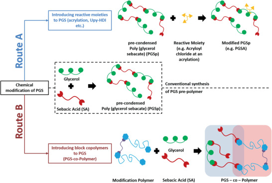
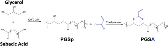
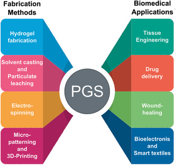
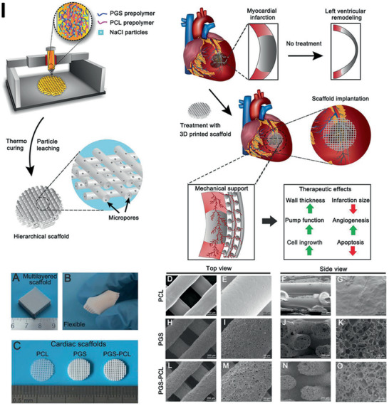
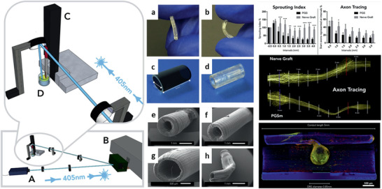
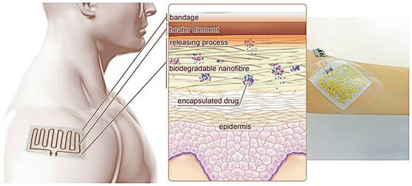
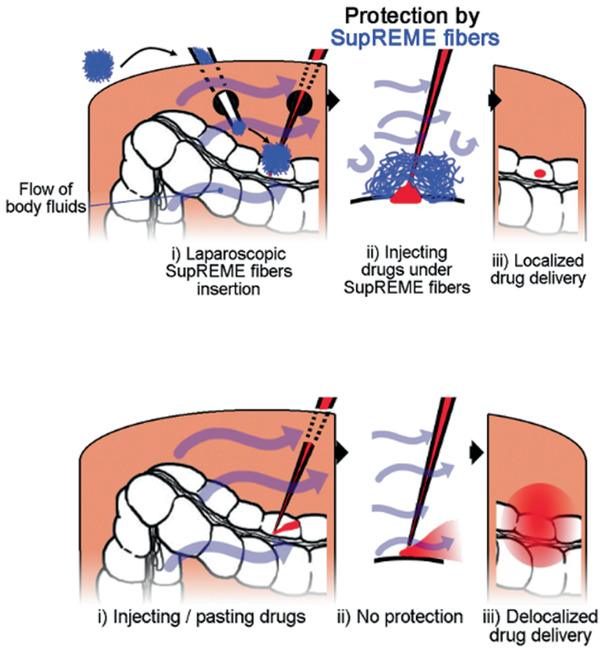
Poly(glycerol sebacate) (PGS) continues to attract attention for biomedical applications owing to its favorable combination of properties. Conventionally polymerized by a two-step polycondensation of glycerol and sebacic acid, variations of synthesis parameters, reactant concentrations or by specific chemical modifications, PGS materials can be obtained exhibiting a wide range of physicochemical, mechanical, and morphological properties for a variety of applications. PGS has been extensively used in tissue engineering (TE) of cardiovascular, nerve, cartilage, bone and corneal tissues. Applications of PGS based materials in drug delivery systems and wound healing are also well documented. Research and development in the field of PGS continue to progress, involving mainly the synthesis of modified structures using copolymers, hybrid, and composite materials. Moreover, the production of self-healing and electroactive materials has been introduced recently. After almost 20 years of research on PGS, previous publications have outlined its synthesis, modification, properties, and biomedical applications, however, a review paper covering the most recent developments in the field is lacking. The present review thus covers comprehensively literature of the last five years on PGS-based biomaterials and devices focusing on advanced modifications of PGS for applications in medicine and highlighting notable advances of PGS based systems in TE and drug delivery.

Keywords: biodegradable polyester; bioelectronics; biomedical applications; composites; poly(glycerol sebacate); tissue engineering.


Conflict of interest statement

The authors declare no conflict of interest.

Figures

Figure 1
Figure 1
Number of published articles of PGS‐based materials during 2015 and the beginning of 2021. Data from WEB OF SCIENCE using POLY (GLYCEROL SEBACATE) in the field “topic” from 2015 to 2021.
Figure 2
Figure 2
Chemical modification of PGS through introducing reactive moieties (Route A) or block copolymers (Route B).
Figure 3
Figure 3
Schematic representation of the chemical synthesis of PGSp and its further modification using trimethylamine to produce acrylated PGS (PGSA). Modified from.[ 27 ]
Figure 4
Figure 4
Representative manufacturing methods and biomedical applications with PGS as the primary material. (Figure generated using Freepik.com).
Figure 5
Figure 5
SEM cross‐section images of produced microchannels on PGS, poly(1,3‐diamino‐2‐hydroxypropane‐co‐polyol sebacate) and PDMS with increasing ablation times. A) Laser ablated 25 times on PGS showing high edge quality B) whereas PDMS presented low edge quality with the same ablation time. Adapted from Hsieh et al. Reproduced under the terms of the CC‐BY license.[ 155 ] Copyright 2017, the Authors. Published by MDPI.
Figure 6
Figure 6
A) Scheme showing the fabrication of micropatterned PGS–aniline trimer (PGS‐AT) films. B) SEM images of flat PGS‐AT films, C) PGS‐AT films with a groove/ridge dimension of 50/50 µm and D) 50/100 µm. E) Scheme of a cellular aspect ratio and F) cellular alignment on the microstructured surface. G) Cellular aspect ratio on different patterned PGS‐AT films. Reproduced with permission.[ 159 ] Copyright 2019, Elsevier.
Figure 7
Figure 7
Scheme showing the microcasting process of PGS films via a patterned silicon wafer and its Teflon overlayer as well as the electrospinning setup, where the silicon wafer replaces the conventional collector (I). SEM images showing different topographical PGS/PCL fiber mats (left) and their corresponding surface roughness profiles (right) (II). Reproduced with permission.[ 110 ] Copyright 2016, Elsevier.
Figure 8
Figure 8
Hierarchical architecture of scaffolds for coculturing vascularized cardiac tissue. Consisting of perfusable channels for human umbilical vein endothelial cells (HUVECs) (red), a vascular–parenchymal interface, and two offset grids with rectangular through‐pores for heart cells (green). Primary and secondary pore structures were generated using micromolding and porogen leaching. A‐E) SEM images show the different porous interfaces (scale bars: A–C), E) 200 µm, D) 500 µm). F) The intensity of Ca2+ signal over time in the selected regions of interest (Construct stained with Fluo‐4AM). Time activation maps showing excitation (K). Heart cell orientation on day 5 shown in confocal micrographs G,H) before and I,J) after pixel‐by‐pixel image analysis. Reproduced with permission.[ 18 ] Copyright 2016, Wiley‐VCH GmbH.
Figure 9
Figure 9
Scheme showing the 3D printing set‐up and mixed ink of PGS and PCL prepolymer with salt particles as well as the therapeutic effects of infarcted hearts when treated with the PGS–PCL scaffolds on infarcted myocardium. A) Images showing a 3D‐printed PGS–PCL scaffold with the multilayer structure as well as the flexibility of B) PGS–PCL scaffolds. C) Different 3D‐printed cardiac patches. Top‐view and cross‐sectional SEM images showing the morphology of D–G) 3D printed PCL, H–K) PGS and L–O) PGS‐PCL scaffolds (scale bars: D), F), H), J), L), N)‐C), E) 200 µm, E), I), M), 50 µm, G), K), O) 20 µm). Reproduced with permission.[ 37 ] Copyright 2019, Wiley‐VCH GmbH.
Figure 10
Figure 10
Scheme of the electrospinning process for the production of artificial vascular grafts. In brief, a polymer solution of PGSp (blue) and PVA (red) is deposited by an applied voltage on a plastic rod (1) and then drawn off on a rotating stainless‐steel mandrel (2). The PGSp–PVA fibers are then thermally cross‐linked and cleaned. Eventually, a PCL solution (violet) is deposited by electrospinning first on an aluminum plate anode (1) and then drawn off onto the rotating cross‐linked PGS core (2). The final result is a composite of an electrospun PGS microfiber core (green) and an electrospun PCL fiber coating (violet) (a). Macroscopic and inset transverse view of a finished graft before implantation, which is shown next to an American dime for size comparison (b). In situ view of a TEVG that conducts blood flow on the day of implantation (c). Representative Doppler ultrasound images of transplanted TEVGs with (top) and without dilatation (bottom) 12 months after implantation. Yellow arrows indicate the proximal anastomosis with the adjacent proximal infrarenal abdominal aorta on the left and the implanted electrospun TEVG on the right (d). 3D reconstruction of a microcomputed tomography image of the same graft. The graft is highlighted in red. The adjacent proximal and distal abdominal aorta is stained white (e). Reproduced with permission.[ 107 ] Copyright 2016, Springer Nature.
Figure 11
Figure 11
Computer‐aided model (Google Sketchup) of the micro‐SLA set‐up by Singh et al. for the production of NGCs. The setup consists of a 405 nm laser [A], a DMD [B], a motorized Z‐table [C] and a container with liquid polymer [D]. a,b) The elastic properties of the mAcr‐PGS NGCs. c) A CAD model (Maya, Autodesk) of an ideal 3D printed NGC. d) A final 3D‐printed and finished product of the NGC, ready for implantation. Scanning electron microscope images show the z‐translation speed of 0.03 mm s‐1 and various laser powers of e) 80 mW, f) 65 mW, g) 30 mW and h) 10 mW. Reproduced under the terms of the CC‐BY 4.0 license.[ 162 ] Copyright 2018, the Authors. Published by Elsevier.
Figure 12
Figure 12
The functional principle of a drug delivery system with integrated heating element and electronics developed by Tamayol et al.[ 19 ] Heat‐sensitive drug nanocarriers were incorporated into nanofibers of technical fabric and were able to deliver their drugs at temperature increase initiated by the integrated, flexible heating element. Reproduced under the terms of the CC‐BY license.[ 19 ] Copyright 2017, the Authors. Published by Springer Nature.
Figure 13
Figure 13
SupREME fibers as an adjuvant for local drug delivery. SupREME fibers facilitate local drug delivery through minimally invasive approaches by shielding the drug from the aqueous environment. This allows the drug to diffuse slowly into the environment and is not immediately washed away by the bloodstream. Reproduced with permission.[ 123 ] Copyright 2017, Wiley‐VCH GmbH.

References

    1. Gadomska‐Gajadhur A., Wrzecionek M., Matyszczak G., Piętowski P., Więcław M., Ruśkowski P., Org. Process Res. Dev. 2018, 22, 1793.
    1. Wang Y., Ameer G. A., Sheppard B. J., Langer R., Nat. Biotechnol. 2002, 20, 602. - PubMed
    1. Martín‐Cabezuelo R., Rodríguez‐Hernández J. C., Vilariño‐Feltrer G., Vallés‐Lluch A., Polymers 2021, 13, 382. - PMC - PubMed
    1. Rai R., Tallawi M., Grigore A., Boccaccini A. R., Prog. Polym. Sci. 2012, 37, 1051.
    1. Matyszczak G., Wrzecionek M., Gadomska‐Gajadhur A., Ruśkowski P., Org. Process Res. Dev. 2020, 24, 1104.

Publication types