Review
. 2021 Mar 9;13(5):1182.
doi: 10.3390/cancers13051182.

Radiobiological Studies of Microvascular Damage through In Vitro Models: A Methodological Perspective

Affiliations
Review

Radiobiological Studies of Microvascular Damage through In Vitro Models: A Methodological Perspective

Luca Possenti et al. Cancers (Basel). .

Abstract

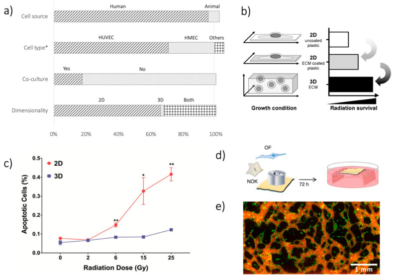
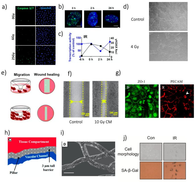
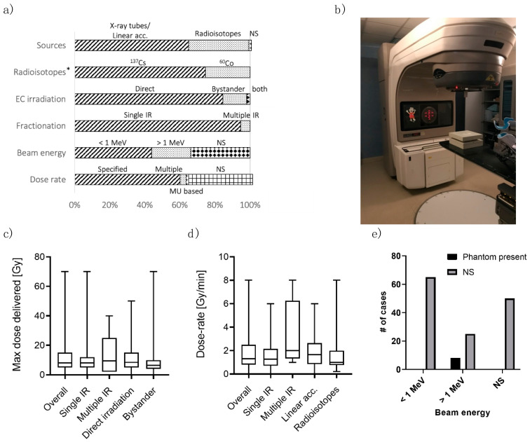
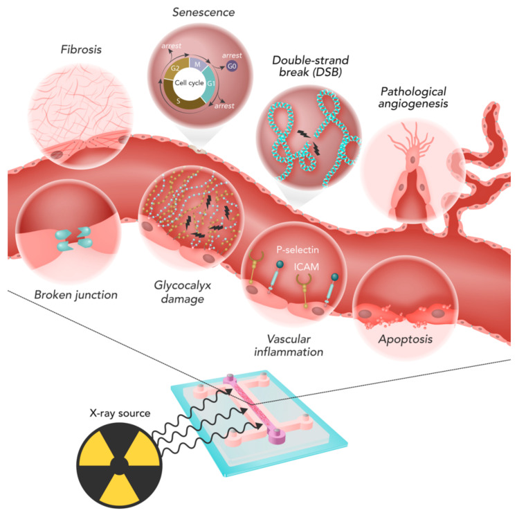
Ionizing radiation (IR) is used in radiotherapy as a treatment to destroy cancer. Such treatment also affects other tissues, resulting in the so-called normal tissue complications. Endothelial cells (ECs) composing the microvasculature have essential roles in the microenvironment's homeostasis (ME). Thus, detrimental effects induced by irradiation on ECs can influence both the tumor and healthy tissue. In-vitro models can be advantageous to study these phenomena. In this systematic review, we analyzed in-vitro models of ECs subjected to IR. We highlighted the critical issues involved in the production, irradiation, and analysis of such radiobiological in-vitro models to study microvascular endothelial cells damage. For each step, we analyzed common methodologies and critical points required to obtain a reliable model. We identified the generation of a 3D environment for model production and the inclusion of heterogeneous cell populations for a reliable ME recapitulation. Additionally, we highlighted how essential information on the irradiation scheme, crucial to correlate better observed in vitro effects to the clinical scenario, are often neglected in the analyzed studies, limiting the translation of achieved results.

Keywords: in-vitro model; ionizing radiation; microenvironment; microvasculature; organ-on-chip; radiobiological models; radiotherapy.


Conflict of interest statement

The authors declare no conflict of interest.

Figures

Figure 1
Figure 1
(a) Summary of analysis in terms of cell source (human vs. animal); cell type (HUVECs, HMECs, others); co-culture systems (yes vs. no); dimensionality of the models (2D, 3D, both). The First 2 bars exceed 100%, given that in some studies, multiple options were considered, e.g., using various cell types. *Cell type analysis is limited to human sources. (b) Difference in IR-related damage when considering 2D and 3D culture systems—reprinted from [22], with permission from Elsevier. (c) Results from [23], showing different apoptosis on EC culture after IR, as a function of the delivered dose (Gy), when using 2D and 3D cultures. Reprinted with permission from [23], © 2019 WILEY-VCH Verlag GmbH & Co. KGaA, Weinheim, Germany. (d) Schematic of the TEOM in-vitro model used in [24]. Reprinted under a Creative Commons Attribution-Non-Commercial-Share Alike 3.0 Unported License. (e) Images of GFP-positive EC (green) organized in a microvascular network on a chip and its perfusion by fluorescent dextran (red), from unpublished data of the authors. * p < 0.05, ** p < 0.01.
Figure 4
Figure 4
Representative images of different analyses. (a) Images of HUVEC apoptosis staining by caspase 3/7 24 h after irradiation. Reprinted with permission from [23], © 2019 WILEY-VCH Verlag GmbH & Co. KGaA, Weinheim, Germany. (b) γ-H2AX foci (green) in HUVEC nuclei (stained with DAPI, blue) after 20 Gy irradiation with 137Cs source. White bars: 5 µm. Reprinted from [30], with permission from Elsevier. (c) γ-H2AX foci overtime referred to figures in b the “−6 h” measure provides a reference before irradiation. The figure also includes data regarding transcriptional inhibition. Reprinted from [30], with permission from Elsevier. (d) Example of the tube formation assay in Matrigel® with dermal HMEC. Reprinted with permission from [78]. © 2008 Institut Gustave Roussy UPRES EA 27–10 Journal compilation © 2008 Blackwell Publishing Ltd. (Hoboken, NJ, USA). (e) Schematic illustration of the Transwell and the wound healing test for HUVEC migration assessment, in case of low (top) and high (bottom) migration. Reprinted from [57], under the Creative Commons Attribution 4.0 International License. (f) Wound healing assay with HUVECs treated with conditioned media from MCF-7, 48 h after the insert removal. Reprinted from [57], under the Creative Commons Attribution 4. 0 International License. (g) Images of junction proteins expression in a HUVEC. Left: ZO-1. Right: PECAM. Reprinted from [15], with permission from Elsevier. (h) Schematic drawing of the approach found in [106]. Reprinted with permission from [106]. © FASEB. (i) Microscope image of the ECs in the network. Scale bar: 250 µm. Figure adapted from [106]. Reprinted with permission from [106]. © FASEB. (j) SA-β-Gal activity assay after 6 Gy photon irradiation and its quantification. Reprinted from [107], with permission from Elsevier.
Figure 2
Figure 2
(a) Summary of the analysis in terms of (i) IR sources; (ii) Radioisotopes; (iii) modality of EC irradiation; (iv) possible fractionation of irradiation; (v) energy of the photon beam; and (vi) dose rate. * 100% is 51 studies, which involve radioisotope as IR source. (b) Picture of a DBX Varian linear accelerator, with an IR phantom placed to irradiate the sample. (c) Boxplot showing the distribution of the maximum dose delivered [Gy] in the studies. Max dose is also analyzed as a fractionation function (Single IR/ Multiple IR) and irradiation type (Direct/ Bystander). (d) Dose rate distribution in the studies. Dose rate is also analyzed as a fractionation function (Single IR vs. Multiple IR) and the source of IR (X-ray tubes/Linear accelerator vs. Radioisotopes). (e) Presence of the IR phantom related to the beam’s energy (less than 1 MeV, higher than 1 MeV, and not specified-NS).
Figure 3
Figure 3
Main phenomena involved in ECs damage due to irradiation: apoptosis, pathological angiogenesis, inflammation, DNA damage, in particular double-strand breaks (DSB), glycocalyx damage, senescence, broken endothelial junctions, and fibrosis.

References

    1. De Ruysscher D., Niedermann G., Burnet N.G., Siva S., Lee A.W.M., Hegi-Johnson F. Radiotherapy toxicity. Nat. Rev. Dis. Prim. 2019;5:13. doi: 10.1038/s41572-019-0064-5. - DOI - PubMed
    1. Rancati T., Fiorino C. Modelling Radiotherapy Side Effects. CRC Press; Boca Raton, FL, USA: 2019.
    1. Barker H.E., Paget J.T.E., Khan A.A., Harrington K.J. The tumour microenvironment after radiotherapy: Mechanisms of resistance and recurrence. Nat. Rev. Cancer. 2015;15:409–425. doi: 10.1038/nrc3958. - DOI - PMC - PubMed
    1. Van Beijnum J.R., Rousch M., Castermans K., Van Der Linden E., Griffioen A.W. Isolation of endothelial cells from fresh tissues. Nat. Protoc. 2008;3:1085–1091. doi: 10.1038/nprot.2008.71. - DOI - PubMed
    1. Huh D., Hamilton G.A., Ingber D.E. From Three-Dimensional Cell Culture to Organs-on-Chips. Trends Cell Biol. 2011;21:745–754. doi: 10.1016/j.tcb.2011.09.005. - DOI - PMC - PubMed

LinkOut - more resources