Review
. 2021 Mar 30;21(7):2391.
doi: 10.3390/s21072391.

Ground Moving Target Imaging via SDAP-ISAR Processing: Review and New Trends

Affiliations
Review

Ground Moving Target Imaging via SDAP-ISAR Processing: Review and New Trends

Marco Martorella et al. Sensors (Basel). .

Abstract

Ground moving target imaging finds its main applications in both military and homeland security applications, with examples in operations of intelligence, surveillance and reconnaissance (ISR) as well as border surveillance. When such an operation is performed from the air looking down towards the ground, the clutter return may be comparable or even stronger than the target's, making the latter hard to be detected and imaged. In order to solve this problem, multichannel radar systems are used that are able to remove the ground clutter and effectively detect and image moving targets. In this feature paper, the latest findings in the area of Ground Moving Target Imaging are revisited that see the joint application of Space-Time Adaptive Processing and Inverse Synthetic Aperture Radar Imaging. The theoretical aspects analysed in this paper are supported by practical evidence and followed by application-oriented discussions.

Keywords: GMTI; ISAR; SAR; STAP; radar; radar imaging.


Conflict of interest statement

The authors declare no conflict of interest.

Figures

Figure 1
Figure 1
Multichannel ISAR geometry.
Figure 2
Figure 2
Attenuation factor. (a) The attenuation term J(y1) is shown for the radar center-scene distance, R0 = 5 km, a carrier frequency, f0 = 10 GHz. (b) Represent a zoom-in version of subplot(a) Reproduced with permission from Alessio Bacci, Optimal Space Time Adaptive Processing for Multichannel Inverse Synthetic Aperture Radar Imaging, PhD Thesis; published by University of Pisa and University of Adelaide, Australia 2014.
Figure 2
Figure 2
Attenuation factor. (a) The attenuation term J(y1) is shown for the radar center-scene distance, R0 = 5 km, a carrier frequency, f0 = 10 GHz. (b) Represent a zoom-in version of subplot(a) Reproduced with permission from Alessio Bacci, Optimal Space Time Adaptive Processing for Multichannel Inverse Synthetic Aperture Radar Imaging, PhD Thesis; published by University of Pisa and University of Adelaide, Australia 2014.
Figure 3
Figure 3
Processing chain of detection and refocusing processor.
Figure 4
Figure 4
ISAR processing chain.
Figure 5
Figure 5
Acquisition geometry relative to a multichannel side-looking SAR system.
Figure 6
Figure 6
Optimum SDAP ISAR functional block.
Figure 7
Figure 7
SAR image of the observed area formed via the range Doppler algorithm (RDA). The red box include the area of interest.
Figure 8
Figure 8
Image of the area under test (a) RDA SAR image—the yellow box includes the training area used for the clutter covariance matrix estimation, (b) Optical Google image of the area under test.
Figure 9
Figure 9
SAR image after clutter suppression via SDAP in which the detected targets are highlighted in the yellow, blue, green and red boxes. A smaller number of available slow-time samples is exploited since SDAP is computationally burdensome when a standard PC is used.
Figure 10
Figure 10
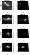
Target refocus through ISAR processing of Target 1 (yellow box in Figure 9) (a,b), Target 2 (blue box in Figure 9) (c,d), Target 3 (green box in Figure 9) (e,f) and Target 4 (red box in Figure 9) (g,h), respectively. (a,c,e,g) Before ISAR, (b,d,f,h) After ISAR.
Figure 11
Figure 11
SAR images with refocused targets. (a) SAR image with a reduced number of samples after SDAP. (b) RDA SAR image with a superimposed refocused targets.
Figure 12
Figure 12
SDAP filter in the radial velocity domain.
Figure 13
Figure 13
Acquisition geometry with a multichannel side-looking SAR system.
Figure 14
Figure 14
Data rearrangement.
Figure 15
Figure 15
Clutter suppression results. (a) SAR image of the observed area. The area under test is included in the red box while the training area is highlighted within the yellow box. (b) SAR image of the area under test. (c) SAR image after clutter suppression via virtual SDAP. (d) SAR image after clutter suppression via SDAP.
Figure 16
Figure 16
Zoom-in of the SAR image after clutter suppression. (a) Clutter suppression via conventional SDAP where two actual channels are employed. (b) Clutter suppression via virtual SDAP where three channels are virtualised and used.
Figure 17
Figure 17
SDAP filter in the radial velocity domain. The blue trend represents the two-channel physical SDAP filter while the red trend represents the three-channel virtual SDAP filter. V-SDAP allows for a narrower filter bandwidth to be obtained and thus for targets with lower radial velocities to be detected.
Figure 18
Figure 18
Rule-based cognitive radar architecture.
Figure 19
Figure 19
RDA SAR image of the observed area. The red box highlights the area under test.
Figure 20
Figure 20
A representation of the content of the system memory. (a) initial memory content in which only a priori information are present. (b) the memory content after the image has been divided into sub-blocks: New clutter classes have been detected.
Figure 21
Figure 21
Performance evaluation of the SAR image after image segmentation: SAR is divided into sub-blocks to detect the presence of an additional classes not stored in the system memory. The sub-blocks containing new classes are highlighted in red.
Figure 22
Figure 22
Segmentaed SAR image after a new segmentation step in which the memory has been updated with new textures belonging to new classes of clutter.
Figure 23
Figure 23
SAR image under test in which the training area is included in the green box, while the area on which to apply SDAP is included in the blue box.
Figure 24
Figure 24
Result of the GIP test applied on the training data set.
Figure 25
Figure 25
Result of the cognitive SDAP processing (a) Original SAR image of the area under test before clutter suppression, (b) SAR image after clutter suppression through SDAP.
Figure 26
Figure 26
Refocusing through ISAR processing of Target 1 (a) before ISAR, (b) after ISAR and of Target 2 (c) before ISAR, (d) after ISAR.
Figure 27
Figure 27
Filter comparison between cognitive SDAP filter and an ideal one.

References

    1. Carrara W., Goodman R., Majewski R. Spotlight Synthetic Aperture Radar: Signal Processing Algorithms. Artech House Signal Processing Library, Artech House; London, UK: 1995.
    1. Martorella M., Giusti E., Berizzi F., Bacci A., Dalle Mese E. ISAR based techniques for refocusing non-cooperative targets in SAR images. IET Radar Sonar Navig. 2012;6:332–340. doi: 10.1049/iet-rsn.2011.0310. - DOI
    1. Lazarov A.D., Minchev C.N. SAR Imaging of a Moving Target; Proceedings of the 2007 3rd International Conference on Recent Advances in Space Technologies; Istanbul, Turkey. 14–16 June 2007; pp. 366–372. - DOI
    1. D’Addio E., Bisceglie M.D., Bottalico S. Detection of moving objects with airborne {SAR} Signal Process. 1994;36:149–162. doi: 10.1016/0165-1684(94)90204-6. - DOI
    1. Raney R. Synthetic Aperture Imaging Radar and Moving Targets. IEEE Trans. Aerosp. Electron. Syst. 1971;AES-7:499–505. doi: 10.1109/TAES.1971.310292. - DOI