Review
. 2021 Mar 22;11(3):810.
doi: 10.3390/nano11030810.

An Overview on Anodes for Magnesium Batteries: Challenges towards a Promising Storage Solution for Renewables

Affiliations
Review

An Overview on Anodes for Magnesium Batteries: Challenges towards a Promising Storage Solution for Renewables

Federico Bella et al. Nanomaterials (Basel). .

Abstract

Magnesium-based batteries represent one of the successfully emerging electrochemical energy storage chemistries, mainly due to the high theoretical volumetric capacity of metallic magnesium (i.e., 3833 mAh cm-3 vs. 2046 mAh cm-3 for lithium), its low reduction potential (-2.37 V vs. SHE), abundance in the Earth's crust (104 times higher than that of lithium) and dendrite-free behaviour when used as an anode during cycling. However, Mg deposition and dissolution processes in polar organic electrolytes lead to the formation of a passivation film bearing an insulating effect towards Mg2+ ions. Several strategies to overcome this drawback have been recently proposed, keeping as a main goal that of reducing the formation of such passivation layers and improving the magnesium-related kinetics. This manuscript offers a literature analysis on this topic, starting with a rapid overview on magnesium batteries as a feasible strategy for storing electricity coming from renewables, and then addressing the most relevant outcomes in the field of anodic materials (i.e., metallic magnesium, bismuth-, titanium- and tin-based electrodes, biphasic alloys, nanostructured metal oxides, boron clusters, graphene-based electrodes, etc.).

Keywords: Mg metal; Sn-Bi alloy; anode; magnesium battery; post-Li battery.


Conflict of interest statement

The authors declare no conflict of interest.

Figures

Figure 1
Figure 1
(A) Difference between electricity demand and photovoltaic electricity produced during a typical spring day and in different years in the Californian grid; (B) “Duck curve” showing energy storage to capture energy during overgeneration risk period (green area) and discharging said energy during peak net load hours (red area); (C) Evolution scenarios of the global car fleet, including combustion vehicles (ICE), liquefied or compressed natural gas (LPG/CNG), hybrid (HEV), plug-in hybrid (PHEV), electric with batteries (BEV), electric with fuel cells (Fuel cell). Adapted with permission from [27,28,29]. Copyright California ISO (2013), Stanford University (2015) and IFP Energies Nouvelles (2018).
Figure 2
Figure 2
Distribution of lithium resources in 2019. Adapted with permission from [86]. Copyright Edison, 2019.
Figure 3
Figure 3
Scheme and working principle of a magnesium rechargeable battery. Adapted with permission from [105]. Copyright John Wiley & Sons, Inc., 2020.
Figure 4
Figure 4
End-of-life recycling rate of some elements of the periodic table. Adapted with permission from [109]. Copyright UNEP, 2011.
Figure 5
Figure 5
The metal/electrolyte interfaces for (A,B) magnesium- and (C) lithium-based systems. Different from lithium, magnesium experiences passivation when the metal is exposed to conventional electrolytes (case A, e.g., with ionic salts and polar solvents), while magnesium passivation does not occur in ethereal organo-magnesium electrolytes (case B, e.g., with Grignard-based solutions). Adapted with permission from [71]. Copyright Beilstein-Institut, 2014.
Figure 6
Figure 6
Scanning electron microscopy (SEM) micrographs of electrodeposited magnesium at different current densities: (a) 0.5 mA cm−2; (b) 1.0 mA cm−2; (c) 2.0 mA cm−2; (d) 0.5 mA cm−2; (e) 1.0 mA cm−2 and (f) 2.0 mA cm−2. Adapted with permission from [146]. Copyright Elsevier B.V., 2011.
Figure 7
Figure 7
Electrochemical performances of bismuth NTs as anodes for MIBs: (a) Cyclic voltammograms (CV) of magnesium ions insertion/deinsertion; (b) Discharge/charge profile of a cell; (c) Rate performance of a cell; (d) Cycling stability and Coulombic efficiency of bismuth NTs for reversible magnesium ions insertion/deinsertion (C-rate was not reported by the authors). Cell configuration: Mg/Mg(BH4)2 0.1 M + LiBH4 1.5 M in diglyme/Bi. A comparison with the corresponding microstructured anodes is also shown in each plot. Adapted with permission from [161]. Copyright American Chemical Society, 2014.
Figure 8
Figure 8
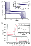
(A) Galvanostatic curve at 2C, after initial activation sweeps, obtained with copper foil supported electrode based on micrometric bismuth particles embedded by carbon additives. Inset: evolution of discharge and charge capacities and Coulombic efficiency. (B) First cycle galvanostatic magnesiation/de-magnesiation curves for Sn/Mg and Bi/Mg half cells (with organohaloaluminate electrolyte); inset: XRD spectra for (1) as-fabricated tin, (2) magnesiated tin (or Mg2Sn—peak positions marked with arrows) and (3) de-magnesiated Mg2Sn. Adapted with permission from [162]. Copyright Royal Society of Chemistry, 2015. Adapted with permission from [26]. Copyright Informa UK Limited, 2017.
Figure 9
Figure 9
Comparison of electrochemical behaviour of tin–antimony alloy and tin towards magnesiation/de-magnesiation: (A) CV carried out at 0.05 mV s−1; (B) Charge–discharge profiles at 50 mA g−1; (C) Specific capacity at different current densities when using the tin–antimony alloy; (D) Cycling stability of the tin–antimony alloy at 500 mA g−1. Adapted with permission from [167]. Copyright American Chemical Society, 2015.
Figure 10
Figure 10
(A) The increased grain boundaries on the atomic scale after the first cycle and the enhanced magnesium ions transport; SEM images of (B) NP-Bi6Sn4 and (C) NP-Bi4Sn6; (D) CV curves for NP-bismuth and alloy electrodes at a scan rate of 0.05 mV s−1 and for NP-tin at 0.01 mV s−1 for the first cycle; (E) Discharge/charge profiles for NP-bismuth and alloy electrodes acquired at 50 mA g−1 and for NP-tin at 20 mA g−1. Adapted with permission from [170]. Copyright Elsevier B.V., 2018.
Figure 11
Figure 11
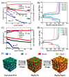
(A) Rate performance for NP-bismuth and alloy electrodes; (B) Discharge/charge profiles for NP-Bi6Sn4 electrode at different current densities; (C) Cycling stability of NP-bismuth and alloy electrode at 200 mA g–1 and of NP-tin at 20 mA g–1; (D) Discharge/charge profiles of NP-Bi6Sn4 electrode for different cycles at 200 mA g–1; (E) Schematic illustration of the electrochemical reaction mechanisms of alloy electrodes. Adapted with permission from [170]. Copyright Elsevier B.V., 2018.
Figure 12
Figure 12
Transmission electron microscopy (TEM) images of (A) Na2Ti3O7 NWs and (B) Na2Ti6O13 NWs; (C) Cycling performance of Na2Ti3O7 and Na2Ti6O13 NWs at 0.1 A g−1. Adapted with permission from [177]. Copyright American Chemical Society, 2020.
Figure 13
Figure 13
(A) Low- and (B) high-magnification SEM images and (C) TEM image of the Ti–Nb2O5 NFs; (D) Operating principle of the magnesium-ion dual-ion battery and (E) its long-term cycling performance at 3C with Ti–Nb2O5 NFs as anode. Adapted with permission from [177]. Copyright American Chemical Society, 2020.
Figure 14
Figure 14
(A) Cycling properties of VO2 NWs in MgSO4 electrolyte; (B) TEM micrograph of the anode before cycling; (C) Relaxed geometries of fully Mg decorated of bare and halide encapsulated B40 (B in pink, Mg in green); (D) Top and side views of the most stable configuration for five Mg atoms adsorption on a C2N monolayer (yellow, orange and pink balls denote the Mg atoms located in the top, middle and bottom layers from the side view). Adapted with permission from [183,184,185]. Copyright Elsevier B.V. (2019,2021) and Royal Society of Chemistry (2019).

References

    1. Wunderling N., Willeit M., Donges J.F., Winkelmann R. Global warming due to loss of large ice masses and Arctic summer sea ice. Nat. Commun. 2020;11:1–8. doi: 10.1038/s41467-020-18934-3. - DOI - PMC - PubMed
    1. Guzmán A., Pinto-Gutiérrez C., Trujillo M.A. Attention to global warming and the success of envi-ronmental initial coin offerings: Empirical evidence. Sustainability. 2020;12:9885. doi: 10.3390/su12239885. - DOI
    1. Hari V., Rakovec O., Markonis Y., Hanel M., Kumar R. Increased future occurrences of the exceptional 2018–2019 Central European drought under global warming. Sci. Rep. 2020;10:1–10. doi: 10.1038/s41598-020-68872-9. - DOI - PMC - PubMed
    1. Kim S., Lee J.E., Kim D. Searching for the Next New Energy in Energy Transition: Comparing the Impacts of Economic Incentives on Local Acceptance of Fossil Fuels, Renewable, and Nuclear Energies. Sustain. J. Rec. 2019;11:2037. doi: 10.3390/su11072037. - DOI
    1. Martins F., Felgueiras C., Smitkova M., Caetano N. Analysis of Fossil Fuel Energy Consumption and Environmental Impacts in European Countries. Energies. 2019;12:964. doi: 10.3390/en12060964. - DOI

LinkOut - more resources