

Development of broad-band high-reflectivity multilayer film for positron emission tomography system
- PMID: 33828611
- PMCID: PMC8022915
- DOI: 10.1088/1748-0221/13/09/p09016
Development of broad-band high-reflectivity multilayer film for positron emission tomography system
Abstract
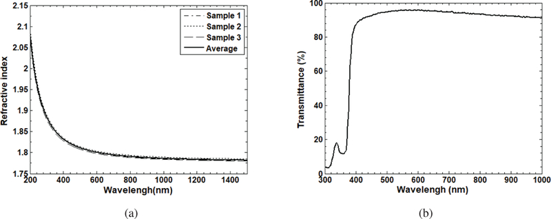
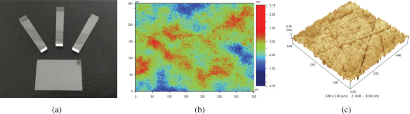
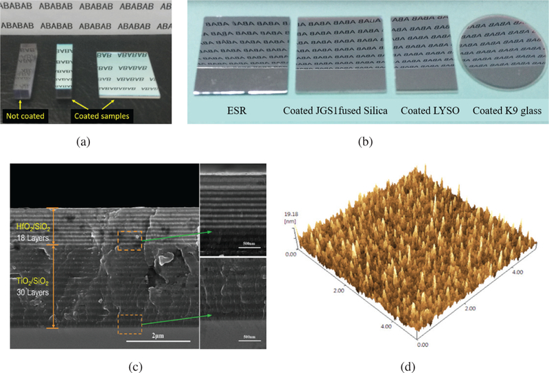
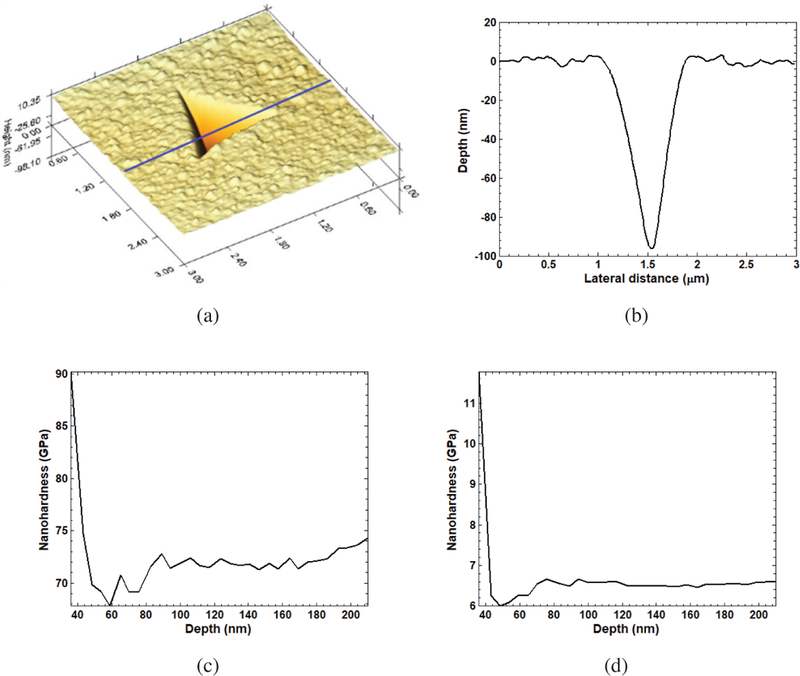
The use of non-ideal reflective materials and low-precision manual manufacturing technologies is a fundamental technical obstacle blocking the positron emission tomography (PET) systems from achieving better performances. We propose to address that long-standing obstacle with advanced multilayer dielectric coating technologies. We designed an broad-band multilayer high-reflectivity (HR) film that can be coated directly on the surface of ultra-precision polished lutetiumyttrium oxyorthosilicate (LYSO) scintillators. The film consists of 48 layers of TiO2/SiO2/HfO2 which are deposited on LYSO scintillator crystal alternately using the electron beam evaporation method. The overall thickness of the HR film is about 3μm. The HR film combines 3 quarter wavelength reflective films, with the central wavelengths of 365 nm, 430 nm and 570 nm respectively, to match the emission spectrum of the LYSO scintillator. The optical experimental results show that the HR film achieved an excellent average reflectivity of 99.50% at 8° incident angle for incident lights with wavelengths between 360 to 620 nm. The average reflectivity at 60° incident angle is higher than 90%. The results of the hardness experiments and the adhesive strength experiments show that the HR film has an excellent mechanical strength. The HR coating technology developed in this study is very attractive because it allows to "print" high-performance reflectors on a scintillator directly with high-precision, instead of manually gluing reflective films on the scintillator. Thus, we conclude that the HR film provides a viable solution to the long standing technical bottleneck that limits the development of high-performance detectors for advanced PET imaging.
Keywords: Detector design and construction technologies and materials; Gamma detectors (scintillators, CZT, HPG, HgI etc); Mirror coating; Optics.
Figures


Similar articles
-
Ultra-precise surface processing of LYSO scintillator crystals for Positron Emission Tomography.Appl Surf Sci. 2019 Mar 1;469:573-581. doi: 10.1016/j.apsusc.2018.11.024. Epub 2018 Nov 9. Appl Surf Sci. 2019. PMID: 33311823 Free PMC article.
-
Performance of long rectangular semi-monolithic scintillator PET detectors.Med Phys. 2019 Apr;46(4):1608-1619. doi: 10.1002/mp.13432. Epub 2019 Feb 20. Med Phys. 2019. PMID: 30723932
-
An edge-readout, multilayer detector for positron emission tomography.Med Phys. 2018 Jun;45(6):2425-2438. doi: 10.1002/mp.12906. Epub 2018 May 6. Med Phys. 2018. PMID: 29635734 Free PMC article.
-
Multilayer Reflective Coatings for BEUV Lithography: A Review.Nanomaterials (Basel). 2021 Oct 20;11(11):2782. doi: 10.3390/nano11112782. Nanomaterials (Basel). 2021. PMID: 34835544 Free PMC article. Review.
-
Radiation detector developments in medical applications: inorganic scintillators in positron emission tomography.Radiat Prot Dosimetry. 2008;129(1-3):13-21. doi: 10.1093/rpd/ncn043. Epub 2008 Mar 5. Radiat Prot Dosimetry. 2008. PMID: 18321877 Review.
Cited by
-
Colored reflectors to improve coincidence timing resolution of BGO-based time-of-flight PET detectors.Phys Med Biol. 2023 Sep 8;68(18):10.1088/1361-6560/acf027. doi: 10.1088/1361-6560/acf027. Phys Med Biol. 2023. PMID: 37579768 Free PMC article.
-
A depth encoding PET detector using four-crystals-to-one-SiPM coupling and light-sharing window method.Med Phys. 2019 Aug;46(8):3385-3398. doi: 10.1002/mp.13603. Epub 2019 Jun 11. Med Phys. 2019. PMID: 31107969 Free PMC article.
-
Ultra-precise surface processing of LYSO scintillator crystals for Positron Emission Tomography.Appl Surf Sci. 2019 Mar 1;469:573-581. doi: 10.1016/j.apsusc.2018.11.024. Epub 2018 Nov 9. Appl Surf Sci. 2019. PMID: 33311823 Free PMC article.
References
-
- Ohira H, Mc Ardle B, Cocker MS, DeKemp RA, DaSilva JN and Beanlands RS, Current and Future Clinical Applications of Cardiac Positron Emission Tomography, Circ. J. 77 (2013) 836. - PubMed
-
- Singhal T, Positron Emission Tomography Applications in Clinical Neurology, Semin. Neurol. 32 (2012) 421. - PubMed
-
- Kuang Z et al., Development of depth encoding small animal PET detectors using dual-ended readout of pixelated scintillator arrays with SiPMs, Med. Phys. 45 (2018) 613. - PubMed
Grants and funding
LinkOut - more resources
Full Text Sources