Review
. 2021 Jun 23;121(12):6915-6990.
doi: 10.1021/acs.chemrev.0c01212. Epub 2021 Apr 9.

Photoclick Chemistry: A Bright Idea

Affiliations
Review

Photoclick Chemistry: A Bright Idea

Benjamin D Fairbanks et al. Chem Rev. .

Abstract

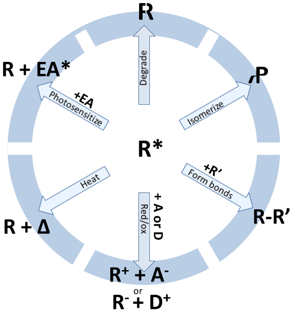
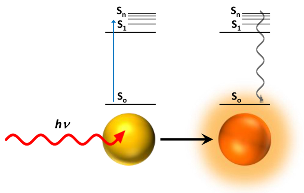
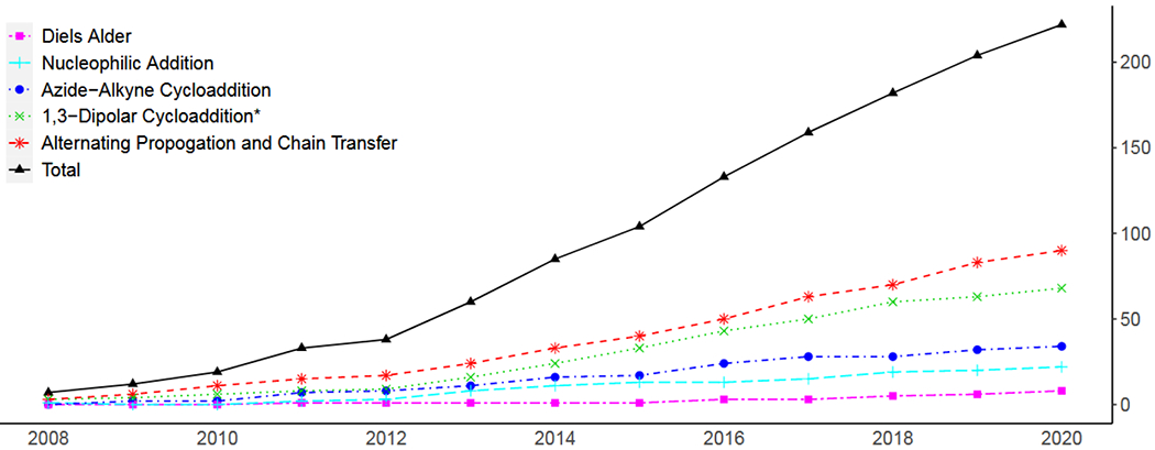
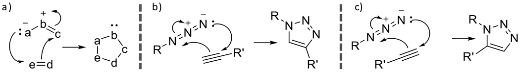
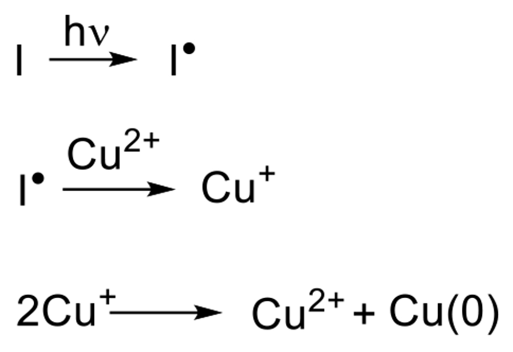
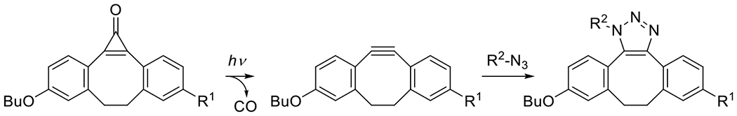
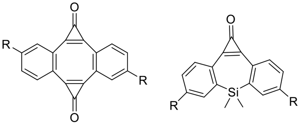
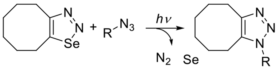
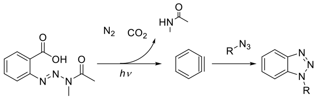
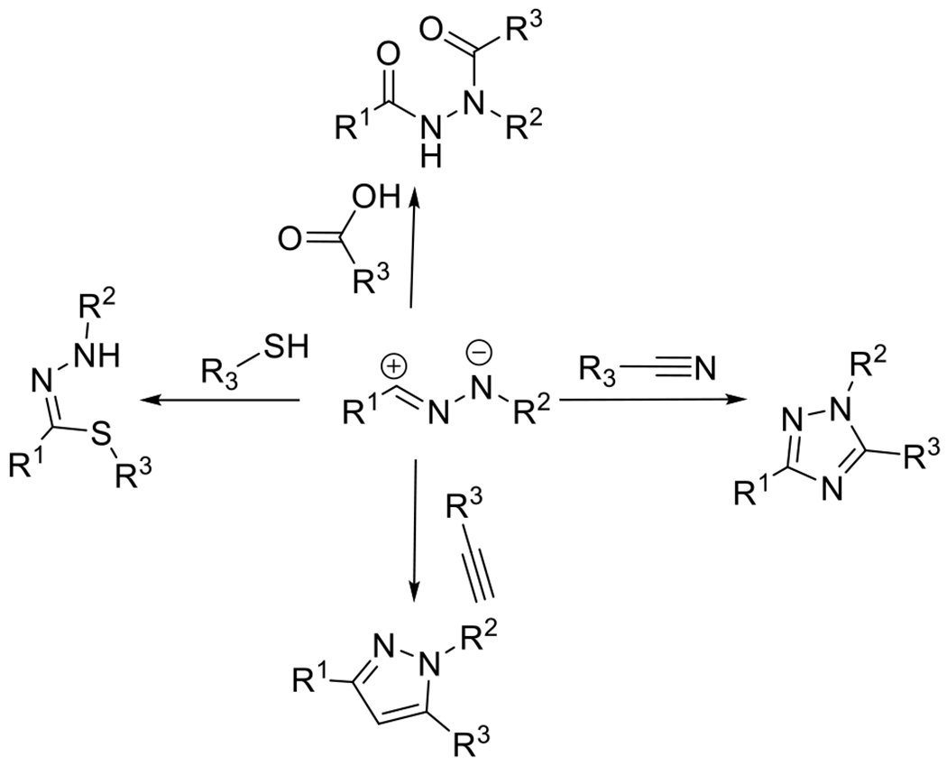
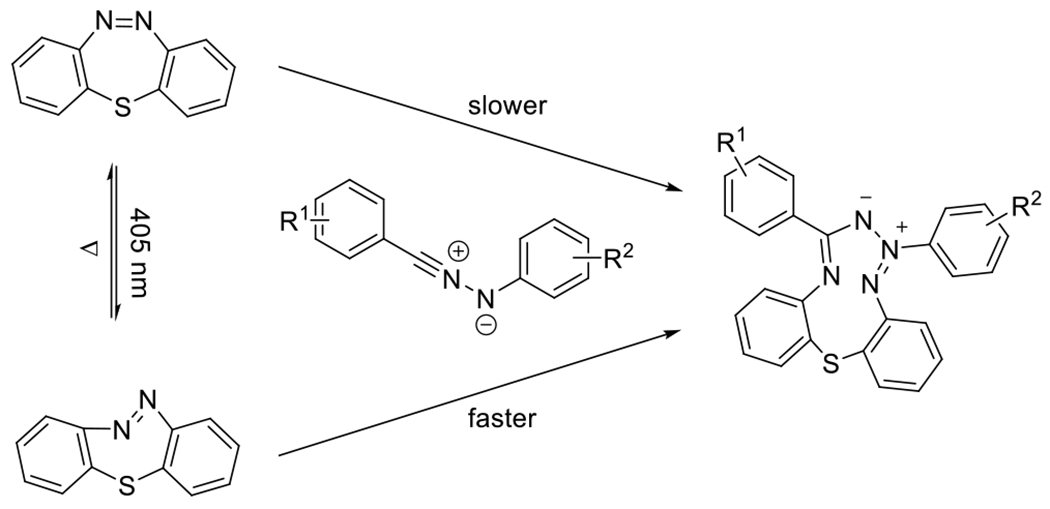
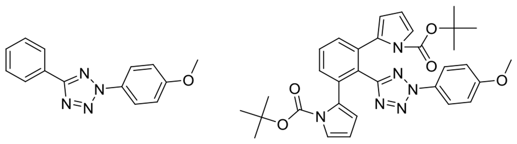
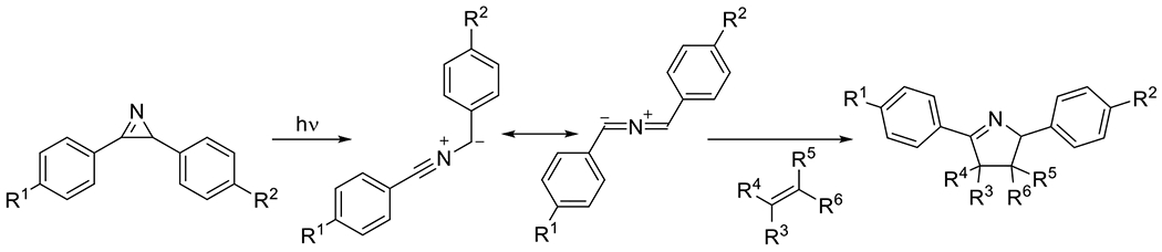
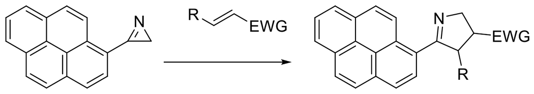
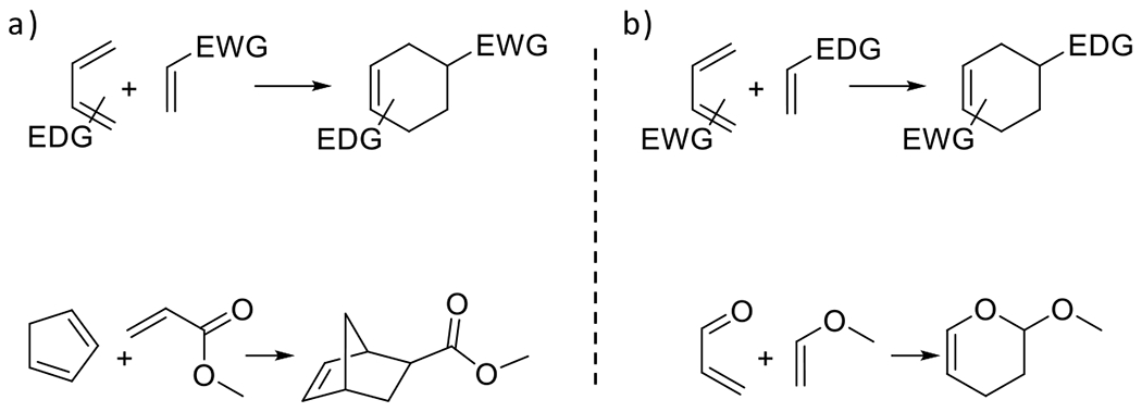
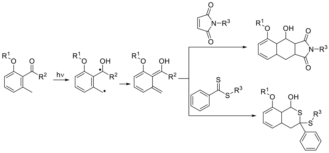
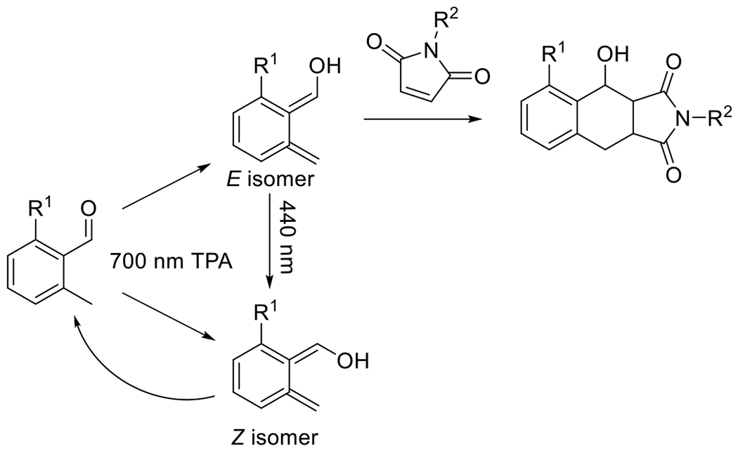
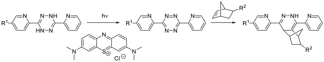
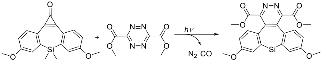
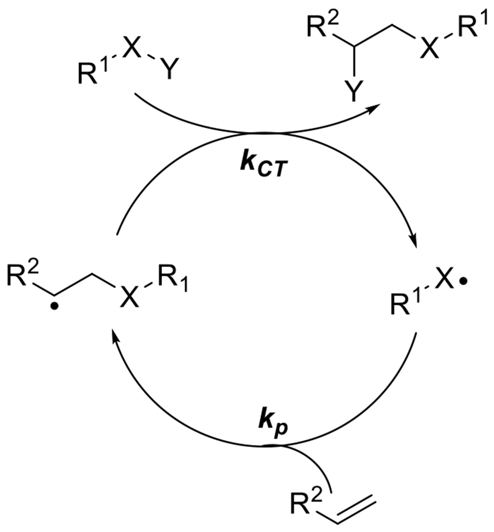
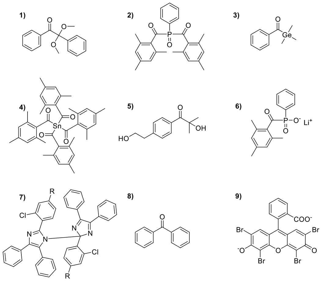
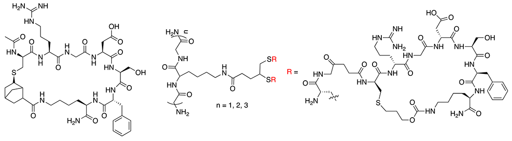
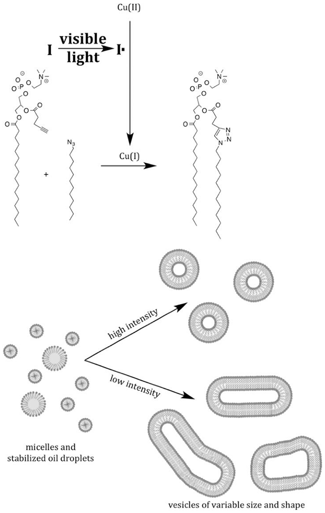
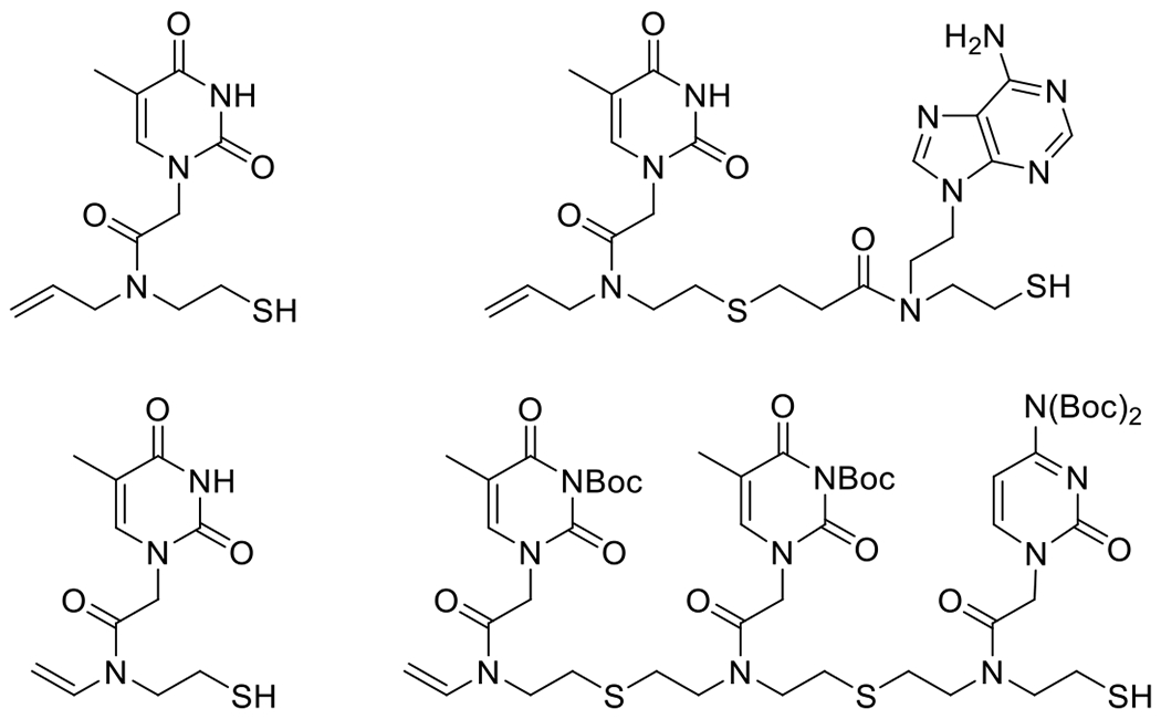
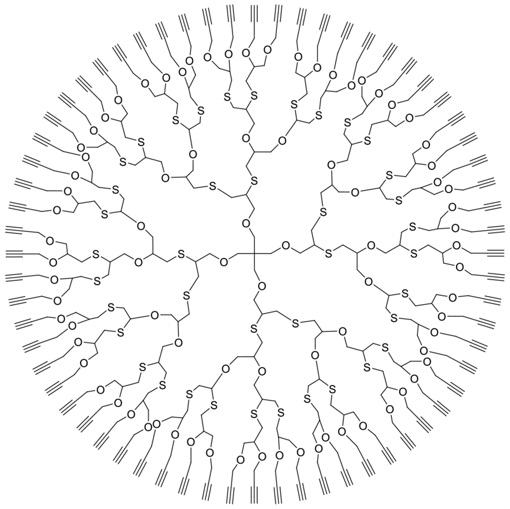
At its basic conceptualization, photoclick chemistry embodies a collection of click reactions that are performed via the application of light. The emergence of this concept has had diverse impact over a broad range of chemical and biological research due to the spatiotemporal control, high selectivity, and excellent product yields afforded by the combination of light and click chemistry. While the reactions designated as "photoclick" have many important features in common, each has its own particular combination of advantages and shortcomings. A more extensive realization of the potential of this chemistry requires a broader understanding of the physical and chemical characteristics of the specific reactions. This review discusses the features of the most frequently employed photoclick reactions reported in the literature: photomediated azide-alkyne cycloadditions, other 1,3-dipolarcycloadditions, Diels-Alder and inverse electron demand Diels-Alder additions, radical alternating addition chain transfer additions, and nucleophilic additions. Applications of these reactions in a variety of chemical syntheses, materials chemistry, and biological contexts are surveyed, with particular attention paid to the respective strengths and limitations of each reaction and how that reaction benefits from its combination with light. Finally, challenges to broader employment of these reactions are discussed, along with strategies and opportunities to mitigate such obstacles.


Conflict of interest statement

The authors declare no competing financial interest.

Figures

Figure 1.
Figure 1.
Reaction coordinate plotted against energy for uncatalyzed, catalyzed and photo-mediated chemical reactions. Catalysts lower activation energy barriers, facilitating increased reaction rates. In photochemical reactions, absorbed photons put the absorbing species in a higher energy state from which alternative chemical reaction pathways may effectively proceed.
Figure 2.
Figure 2.
General Jablonski diagram for the possible fates of photonic energy absorbed by a photoactivated molecule. Internal conversion is denoted by IC; intersystem crossing, ISC; fluorescence, F; phosphorescence, P; absorbance, A. Also shown are the electron orbitals and spins. Highest occupied molecular orbital is abbreviated HOMO and lowest unoccupied molecular orbital is abbreviated LUMO.
Figure 3.
Figure 3.
Flow chart showing the processes that an absorbing molecule may take with the accompanying potential products and the reaction constants.
Figure 4.
Figure 4.
Jablonski diagram for photosensitization wherein an excited molecule transfers energy from its high energy, excited state, to another molecule, placing it in an excited state while the original molecule relaxes to ground state.
Figure 5.
Figure 5.
Photoactivated species can participate or initiate chemical reactions via one of these six general mechanisms.
Figure 6.
Figure 6.
Two examples of photomediated degradation including photodeprotection of a carboxylic acid (top) and photomediated cleavage of 1-hydroxycyclohexyl phenyl ketone.
Figure 7.
Figure 7.
Photoisomerization of azobenzene wherein high energy UV light isomerizes the trans form to the cis form. Exposure to visible light isomerizes the cis form to the trans form.
Figure 8.
Figure 8.
Photodimerization of thymine (shown) and cytosine in DNA has been implicated in the development of skin cancer.
Figure 9.
Figure 9.
General scheme for photoredox reactions with oxidative quenching shown on the left and reductive quenching shown on the right. In oxidative quenching, the light-activated species loses an electron to an oxidizer, gaining a net positive charge. The photoactive species is regenerated by reduction. In the reductive quenching mechanism, the photoactivated species accepts an electron from a reducer, gaining a net negative charge. The photoactive species is regenerated by oxidation.
Figure 10.
Figure 10.
Photothermal relaxation of gold nanoparticles, transitioning absorbed photonic energy into thermal energy via internal conversion.
Figure 11.
Figure 11.
Hypothetical light intensity vs sample depth diagrams for a reaction with high absorbance (left) and low absorbance (right) and intermediate absorbance (middle). Linearity as described by the Beer Lambert is often not observed at high absorptions.
Figure 12.
Figure 12.
Number of journal articles published by year on photoclick chemistry, divided by class of reaction. *indicates 1,3-dipolarcylcoadditions other than azide alkyne cycloadditions.
Figure 13.
Figure 13.
a) general mechanism for 1,3-dipolar cycloaddition wherein rearrangement of electrons between a 1,3-dipole and dipolarophile results in generation of five membered ring structure. b) 1,3-dipolar cycloaddition between an azide (1,3-dipole) and alkyne (dipolarophile) (Huisgen azid alkyne cycloaddition), resulting in 1,4 regioisomer and c) the cycloaddition resulting in the 1,5-regioisomer.
Figure 14.
Figure 14.
a) Original proposed mechanism for Cu(I) catalysis of azide alkyne cycloaddition. Adapted, with permission, from reference . Copyright 2002 John Wiley and Sons. b) Updated mechanism for Cu(I) catalyzed azide alkyne cycloaddition indicating concerted effect of two copper atoms reflecting low experimental yields of copper(I)-acetylide in reactions without exogenous Cu(I). Adapted from reference , with permission, from AAAS, Copyright 2013.
Figure 15.
Figure 15.
Photogeneration of Cu(I) via direct donation of electron from photogenerated radicals. Also depicted is the disproporationation resulting in regeneration of Cu(II) and the formation of Cu(0).
Figure 16.
Figure 16.
Cyanine-based PET catalyst with a barbital group in the meso position employed in the NIR mediated reduction of Cu(II) to Cu(I) and successful catalysis of CuAAC reaction.
Figure 17.
Figure 17.
PcAAC mechanism-the photomediated azide alkyne cycloaddition by direct photooxidation of alkyne and subsequent 1,3-dipolarcycloaddition and regeneration of photocatalyst. Figure adapted, with permission, from reference . Copyright 2020 John Wiley and Sons.
Figure 18.
Figure 18.
Ring strain in cyclooctyne facilitates fast, room temperature, copperless cycloaddtion.
Figure 19.
Figure 19.
The propensity for cycloaddition with azides is increased in cycloalkynes by the destabilization of the alkyne by proximal electron withdrawing groups (e.g. fluorine atoms) and by the increase of sp2 hybridized atoms in the ring.
Figure 20.
Figure 20.
Photoduncaging of cyclooctyne for subsequent strain promoted cycloaddition with organic azide.
Figure 21.
Figure 21.
Other notable cyclopropenone-protected strained alkynes including a photocaged dibenzocyclooctadiyne (dibenzo[a,e]dicyclopropa[c,g][8]annulene-1,6-dione; left) and a photocaged dibenzosilacycloheptyne (6,6-dimethyldibenzo[b,f]cyclopropa[d]silepin-1(6H)-one; right).
Figure 22.
Figure 22.
PhotoSPAAC reaction using selenadiazole photocaging group.
Figure 23.
Figure 23.
Photogeneration of benzyne via decomposition of 2-(3-acetyl-3-methyltriaz-1-en-1-yl)benzoic acid and subsequent conjugation to organic azide.
Figure 24.
Figure 24.
Photosensitized ring-strain generation in cycloheptene, promoting subsequent reaction with benzyl azide.
Figure 25.
Figure 25.
Photomediated decomposition of bisaryl tetrazole to nitrile imine for subsequent participation in 1,3-dipolarcycloaddition.
Figure 26.
Figure 26.
Tuning of photoabsorption profiles can be accomplished by choice of tetrazole substituents.
Figure 27.
Figure 27.
Photoconversion of diaryl sydnone to nitrile imine and subsequent 1,3-dipolarcycloaddition with alkene.
Figure 28.
Figure 28.
Reactions of nitrile imine 1,3-dipole with thiols and carboxylates as well as other dipolarophiles including nitriles and alkynes.
Figure 29.
Figure 29.
Photoisomerization of cis configuration of DBTD to trans configuration of DBTD by irradiation with 405 nm light permits the addition to photogenerated nitrile imine. In contrast to cis DBTD, trans DBTD proves an effective dipolarophile in the reaction.,
Figure 30.
Figure 30.
Photoreactive tetrazole (left) and bulky substituent analog (right). Pendant groups sterically hinder nucleophilic additions and improve selection of 1,3-dipolarcycloaddition adduct with a variety of alkenes.
Figure 31.
Figure 31.
Photogeneration of nitrile ylide from bisaryl azirine and subsequent 1,3-dipolarcycloaddition.
Figure 32.
Figure 32.
Visible light activation of pyrene azirine and conjugation to electron deficient alkenes. EWG = electron withdrawing group. R = H, COOEt, PEG.
Figure 33.
Figure 33.
a) Generalized Diels Alder reaction between electron rich diene and electron deficient dienophile and example of cyclopentadiene reaction with methyl acrylate. b) Generalized inverse electron demand Diels Alder reaction and example of reaction between propenal and methyl vinyl ether.
Figure 34.
Figure 34.
Photoenolization of ortho-methyl phenyl aldehyde and subsequent Diels Alder cycloaddition with dienophilic maleimide (top) or hetero Diels Alder cycloaddition with dithiobenzoate (bottom).
Figure 35.
Figure 35.
Dual wavelength control over the photoenol DA reaction. Two photon absorption at 700 nm generates a mixture of isomers with differing lifetimes while simultaneous exposure to 440 nm converts a long-lived isomer to a short-lived isomer, preventing effective cycloaddition. Figure adapted, with permission, from reference . Copyright 2017 American Chemical Society.
Figure 36.
Figure 36.
General scheme for the photomediated Diels Alder reaction with electron deficient alkynes and subsequent hydroxyl elimination to yield fluorescent naphthalene derivative.
Figure 37.
Figure 37.
Photodegradation of 3-(hydroxymethly)-2-naphtol to 2-naphtoquinone-3-methide and subsequent IEDDA reaction with vinyl ether.
Figure 38.
Figure 38.
Hydrolysis of IEDDA adducts proceeds in either acidic (acetal, top) or even neutral (hemiaminal ether, bottom) aqueous conditions.
Figure 39.
Figure 39.
Naphtoquinone methides are also highly reactive toward thiols, though the reaction is reversible.
Figure 40.
Figure 40.
Conversion of dihydrotetrazine to tetrazine via methylene blue-photocatalyzed oxidation and subsequent IEDDA reaction with norbornene.
Figure 41.
Figure 41.
IEDDA reaction between tetrazine and photogenerated cycloheptyne dienophile.
Figure 42.
Figure 42.
General mechanism for radical alternating propagation, chain transfer reactions wherein radical propagation across a pi bond results in generation of a radical that abstracts an atom from a donor molecule to generate the reaction product.
Figure 43.
Figure 43.
The general mechanism of the photoinitiated thiol–ene coupling, consisting of alternating radical propagation and chain transfer reactions, leading to a one-to-one addition between thiols and alkenes.
Figure 44.
Figure 44.
Structures of representative radical photoinitiators that may be used in thiol-ene and other radical APT reactions: 1) hydrophobic type I photoinitiator, 2,2-dimethoxy-2-phenylacetophenone (DMPA); 2) hydrophobic, type I, bis(2,4,6-trimethylbenzoyl)-phenylphosphineoxide (BAPO, I819); 3) hydrophobic type I photoinitiator benzoyltrimethylgermane (BTG); 4) hydrophobic type I photoinitiator tetrakis(2,4,6-trimethylbenzoyl)stannane; 5) hydrophilic, type I, 2-hydroxy-4′-(2-hydroxyethoxy)-2-methylpropiophenone (I2959); 6) hydrophilic, type I, lithium phenyl-2,4,6-trimethylbenzoylphosphinate (LAP); 7) hydrophobic type I hexaarylbiimidazole (HABI) photoinitiator; 8) hydrophobic, type II, benzophenone, 9) hydrophilic type II initiator, eosin Y.
Figure 45.
Figure 45.
Initiation of thiol-ene reactions with NIR exposure is accomplished by release of initiating radical from upconverting nanoparticles, which, upon absorption of photons, cause the decomposition of the pendant oxime ester coumarin via a combination of FRET and photon upconversion.
Figure 46.
Figure 46.
Relative reaction rates of various alkenes as determined experimentally and reported by Roper and Hoyle.
Figure 47.
Figure 47.
The simplified mechanism of the radical thiol–yne coupling reaction consisting of sequential propagation, chain transfer cycles.
Figure 48.
Figure 48.
Order of alkyne reactivity toward mercaptopropionates. Notable is that while the initial addition rate is fastest in the ring strained cyclooctyne, subsequent addition was not observed.
Figure 49.
Figure 49.
Various photolatent thiolate nucleophile mediated click reactions.
Figure 50.
Figure 50.
Proposed mechanism of the photogeneration of TBD from TBD.HBPh4. Adapted, with permission, from reference . Copyright 2008 American Chemical Society.
Figure 51.
Figure 51.
Mechanism and functional group reactivity consideration for base catalyzed thiolate mediated epoxide ring opening click reaction. Figure adapted, with permission, from reference . Copyright 2020 American Chemical Society.
Figure 52.
Figure 52.
Mechanism of the photolatent base-catalyzed thiol-isocyanate click reaction.
Figure 53.
Figure 53.
Mechanism of a) base and b) nucleophile catalyzed c) thiol-Michael addition click reaction cycle. In the case of photomediated thiol-Michael addition, the base species, B:, is most often generated by photodecomposition of a photolatent base.
Figure 54.
Figure 54.
a) pKa values of commonly used thiols in Michael addition click reaction, b) Reactivities of commonly used vinyl groups in thiol-Michael addition click reactions. ,
Figure 55.
Figure 55.
Photolytic Pathway of NVOC–Amine and NPPOC–Amine Compounds.
Figure 56.
Figure 56.
Photosensitization system for photobase-catalyzed thiol-Michael additions with photosensitizer (ITX) photolatent base (TBD-HBPH4) and radical scavenger (TEMPO) to mitigate homopolymerization of acrylate Michael acceptor.
Figure 57.
Figure 57.
Proposed photolysis mechanism of Coumarin-TMG upon visible light irradiation.
Figure 58.
Figure 58.
Mechanism of Phototriggered Base Proliferation System for Initiating the Thiol-Michael Addition Reaction.
Figure 59.
Figure 59.
Photouncaging thiol and subsequent thiol-Michael addition click reaction.
Figure 60.
Figure 60.
Mechanism of photouncaging of o-NB caged thiol.,
Figure 61.
Figure 61.
General uncaging mechanism of coumarin derived PPGs.,
Figure 62.
Figure 62.
Activation of a locked phototrigger via the reaction with thiol to form an unlocked phototrigger. The reaction of the maleimide substituent with β-mercaptoethanol prevents PET quenching of the phototrigger, allowing subsequent photochemistry to occur. Adapted, with permission, from reference . Copyright 2012 American Chemical Society.
Figure 63.
Figure 63.
Illustration of potential effects of C-3 substitution on photoisomerization process. A methyl group installed in the C-3 position improves photolysis by preventing the migration of the thioether.
Figure 64.
Figure 64.
Nitrodibenzofuran has been shown to be an effective photocaging group for thiols.
Figure 65.
Figure 65.
Mechanism for the photo-Uncaging of thiol-bimane in the presence of an electrophile.
Figure 66.
Figure 66.
Proposed photolysis mechanism for the electron donor-styryl-conjugated coumarin-based PPGs as reported in reference.
Figure 67.
Figure 67.
Schematic representation of photoinduced hydrazone reaction.
Figure 68.
Figure 68.
Photoinduced cleavage of a 2-[(4,5-dimethoxy-2-nitrobenzyl)oxy]tetrahydro-2H-pyranyl derivative and subsequent oxime ligation with hydroxylamine derivatives. R=C3H6COOH.
Figure 69.
Figure 69.
Mechanism and strategy of peptide/protein synthesis using photocaged N-sulfanylethylanilide peptide. Adapted, with permission, from reference . Copyright 2016 American Chemical Society.
Figure 70.
Figure 70.
Products generated via thiol-ene coupling of various thiols with unsaturated glycosides.
Figure 71.
Figure 71.
Cyclic peptides formed via intramolecular thiol-ene (left) and thiol-yne (right) reactions.
Figure 72.
Figure 72.
Examples of bioactive molecules and potential drug candidates generated via the PhotoCuAAC reaction (top) and via the PcAAC reaction (bottom).
Figure 73.
Figure 73.
PhotoCuAAC reaction results in in situ synthesized phospholipids that self assemble into vesicles. Morphology of the resulting vesicles depends on exposure conditions, with high intensity resulting in smaller and more uniform structures. Figure reprinted, with permission, from reference . Copyright 2016 American Chemical Society.
Figure 74.
Figure 74.
Examples of Click Nucleic Acid (CNA) polymerizable nucleobase monomers including first generation thymine monomer (top left), first generation polymerizable TA dimer (top right), second generation thymine monomer (bottom left) and polymerizable TTA trimer (bottom right). ,
Figure 75.
Figure 75.
Dendrimer made via alternating thioglyerol-yne and alkyne conjugation reactions. The thioglycerol-yne coupling results in the introduction of two hydroxyl groups per reaction while the subsequent alkyne coupling replaces the alcohol with the difunctional yne for the next thioglycerol coupling reaction. Each successive reaction pair results in a quadrupling of functionality as each alkyne is difunctional.
Figure 76.
Figure 76.
a) Sequential photo-labeling of azido-BSA with photogenerated ring-strained cyclooctadiyne. b) Selective light-directed Immobilization of rhodamine B on a 96-well plate with photogenerated cyclooctadiyne. In these examples, the photocaged cyclooctadiyne serves as an exogenously activatable crosslinker, permitting the coupling of two azide-containing species. Reprinted, with permission, from reference . Copyright 2016 Royal Society of Chemistry.
Figure 77.
Figure 77.
Photo-IEDDAC labeling on living cells. a) labeling of sfGFP-N150mTetK with photo-11. b) Structures of water-soluble photo-DMBO conjugates. Both photo-11 and the Cy5-conjugate photo-14 are decarbonylated by short irradiation at 365 nm to quantitatively form 11 and 14, respectively. c) Fluorescence imaging and fluorescence microscopy show efficient and light-induced labeling of a cell-surface protein in living E. coli. Reproduced, with permission, from reference . Copyright 2019 John Wiley and Sons.
Figure 78.
Figure 78.
a) schee for labeling DNA of zebrafish via tetrazole-ene photoclick reaction and b) fluorescence microscopy images of cellular DNA spatially labeled through the tetrazine-ene reaction. Reproduced, with permission, from reference . Copyright 2019 American Chemical Society.
Figure 79.
Figure 79.
Thiol-yne modification of BSA. Addition of propargyl 1-thio-β-D- glucopyranoside at thiol present sites on BSA to form alkene functional handles which then react with thiol functional peptide chains and fluorescein. Reproduced, with permission, from reference . Copyright 2011 Royal Society of Chemistry.
Figure 80.
Figure 80.
Schematic representation of the molecular level control of tissue assembly and disassembly via the chemoselective, bio-orthogonal and photoswitchable cell surface engineering approach employing photoinduced oxime ligation and o-nitrobenzyl chemistry. Reproduced, with permission, from reference . Copyright 2014 Springer Nature.
Figure 81.
Figure 81.
Structure of tryptophan (left) with reactive alkene indicated in red. Proposed conjugate linkage (right) between tryptophan-containing protein and tetrazole-terminated PEG.
Figure 82.
Figure 82.
Examples of nonnative amino acids capable of participating in various photoclick reactions.
Figure 83.
Figure 83.
Reactive chemical vapor deposition to prime surface for thiol-ene and thiol-yne surface patterning reactions with thiol-bearing molecules. Reproduced, with permission, from reference . Copyright 2012 John Wiley and Sons.
Figure 84.
Figure 84.
General procedure for photomasked image transfer for microfluidic device fabrication. A mask is placed over monomer mixture and exposed to light. Masked regions form channels and other negative features in the generated device.
Figure 85.)
Figure 85.)
VonKossa MacNeil stained longitudinal sections of the femur defect area at 12 weeks. A sample bridged partially by fibrous tissue (left). A sample bridged by combination of bone and cartilage (right). The poly(propylene fumarate) scaffold stains light blue (indicated by yellow arrows), mineralized tissue stains black (indicated by pink arrow), cartilaginous material stains blue/purple (indicated by orange arrows) and fibrous tissue stains a light blue (red arrow). At the 12 week timepoint there was no evidence of the thiol-ene hydrogel macroscopically or microscopically. Endochondral ossification of cartilage is highlighted in the expanded view of the sample on the right. Reproduced, with permission, from reference . Copyright 2019 John Wiley and Sons.
Figure 86.
Figure 86.
a) iEDDAC network formation using red light (b) Picture of agarose gels used as a dermal model. (c) Change in the storage modulus with the exposure to light. Reproduced, with permission, from reference . Copyright 2017 American Chemical Society.
Figure 87.
Figure 87.
Concept of light-mediated Michael-type addition for spatiotemporally controlled hydrogel crosslinking; a, A thiol-containing macromer is protected with photo-labile caging group and is dissolved in a hydrogel network comprising free vinyl sulfone groups; b, localized laser illumination causes photocleavage of the caging groups reactivating thiols; c, activated thiol-containing PEGs react to vinyl sulfone via Michael-type addition reaction creating localized stiffness patterns. Reproduced, with permission, from reference . Copyright 2012 Royal Society of Chemistry.
Figure 88.
Figure 88.
i) General procedure for the fabrication and functionalization of the PEG based hydrogels. (1) Precursor solution placed between a methacrylate functional glass slide and PDMS cover. (2) Irradiated under blue light to obtain the crosslinked gel. (3) Gel swollen with acrylate solution and photomask placed on top. (4) Irradiated under UV light to obtain patterned sections. (a) Hydrogel precursor solution. 1 : 1 equivalent of DTT and norbornene moieties. (b) Crosslinks consist of a double thioether linkage. (c) Chemistry of the photopatterned areas. ii)Surface adhesion of NHDF cells. (a) DIC image of NHDF cells after 24 h incubation on the hydrogel surface. (b) Fluorescence confocal image of the photopatterned section of the gel (photopatterned areas appear black). (c) Fluorescence confocal image of NHDF cells stained with propidium iodide. (d) Merged image of (b) and (c). Reproduced, with permission, from reference . Copyright 2018 Royal Society of Chemistry.
Figure 89.
Figure 89.
Schematic representation of multiphoton chemical patterning in hydrogel. Reproduced from reference . Copyright 2008 American Chemical Society.
Figure 90.
Figure 90.
a) Schematic representation of sequential photorelease of thiols and bioconjugations with protein and QDs in one-pot process. (b, c) UV-vis spectra of CNTP (PBS, pH = 7.4) upon 420 nm irradiation and followed 365 nm irradiation. (d) Pictures are TOPO-QDs, unpurified QDs–CNTP–avidin and purified QDs–CNTP–avidin after centrifugation (from left to right) Reproduced from reference . Copyright 2014 Royal Society of Chemistry.
Figure 91.
Figure 91.
Mouse as a test structure: (a) CAD model, 3D printed N19T06–060 visualized by (b) light microscope and (c) laser scanning microscope using PVA thiol-ene material. Adapted, with permission, from reference . Copyright 2016 John Wiley and Sons. d) schematics of the 2PP microfabrication; (e) z-stacked laser scanning microscope image of a 3D “Octopus” construct produced by 2PP of HA-VE/DTT. Reproduced, with permission, from reference . Copyright 2014 Royal Society of Chemistry.
Figure 92.
Figure 92.
(a) Schematic of the microfluidic device-based microgel production procedure. (b) Schematic illustrating microgel extrusion into a 3 mm rectangular mold and microgel annealing into scaffolds. (c) Image showing gradient MAP scaffolds injected into a mouse femoral defect. (d) Z projection images of hMSC proliferation and spreading in MAP scaffolds with either a stiffness gradient (top) or a degradability gradient (bottom). Green represents F-actin and blue represents nuclei. Reproduced, with permission, from reference . Copyright 2020 John Wiley and Sons.
Figure 93.
Figure 93.
Schematic representation of liposome templated synthesis of PEG-based nanogels via photo triggered thiol-maliemide click reaction in aqueous media (1) DI water, polycarbonate membrane; (2) 365 nm @ 10 mW/cm2, 2 h. and TEM images of the lipid-coated nanogels dried from aqueous solution. Reproduced, with permission, from reference . Copyright 2014 Royal Society of Chemistry.

References

    1. Tasdelen MA and Yagci Y, Light-Induced Click Reactions, Angew. Chem. Int. Ed, 2013, 52, 5930–5938. - PubMed
    1. Kolb HC, Finn MG, and Sharpless KB, Click Chemistry: Diverse Chemical Function from a Few Good Reactions, Angew. Chem. Int. Ed, 2001, 40, 2004-+. - PubMed
    1. Barner-Kowollik C, Du Prez FE, Espeel P, Hawker CJ, Junkers T, Schlaad H, and Van Camp W, “Clicking” Polymers or Just Efficient Linking: What Is the Difference?, Angew. Chem. Int. Ed, 2011, 50, 60–62. - PubMed
    1. Fairbanks BD, Love DM, and Bowman CN, Efficient Polymer-Polymer Conjugation Via Thiol-Ene Click Reaction, Macromol. Chem. Phys, 2017, 218.
    1. Kärkäs MD, Porco JA, and Stephenson CRJ, Photochemical Approaches to Complex Chemotypes: Applications in Natural Product Synthesis, Chem. Rev, 2016, 116, 9683–9747. - PMC - PubMed

Publication types

LinkOut - more resources