Review
. 2021 Apr 28;121(8):4309-4372.
doi: 10.1021/acs.chemrev.0c01088. Epub 2021 Apr 12.

Soft Materials by Design: Unconventional Polymer Networks Give Extreme Properties

Affiliations
Review

Soft Materials by Design: Unconventional Polymer Networks Give Extreme Properties

Xuanhe Zhao et al. Chem Rev. .

Abstract

Hydrogels are polymer networks infiltrated with water. Many biological hydrogels in animal bodies such as muscles, heart valves, cartilages, and tendons possess extreme mechanical properties including being extremely tough, strong, resilient, adhesive, and fatigue-resistant. These mechanical properties are also critical for hydrogels' diverse applications ranging from drug delivery, tissue engineering, medical implants, wound dressings, and contact lenses to sensors, actuators, electronic devices, optical devices, batteries, water harvesters, and soft robots. Whereas numerous hydrogels have been developed over the last few decades, a set of general principles that can rationally guide the design of hydrogels using different materials and fabrication methods for various applications remain a central need in the field of soft materials. This review is aimed at synergistically reporting: (i) general design principles for hydrogels to achieve extreme mechanical and physical properties, (ii) implementation strategies for the design principles using unconventional polymer networks, and (iii) future directions for the orthogonal design of hydrogels to achieve multiple combined mechanical, physical, chemical, and biological properties. Because these design principles and implementation strategies are based on generic polymer networks, they are also applicable to other soft materials including elastomers and organogels. Overall, the review will not only provide comprehensive and systematic guidelines on the rational design of soft materials, but also provoke interdisciplinary discussions on a fundamental question: why does nature select soft materials with unconventional polymer networks to constitute the major parts of animal bodies?


Figures

Figure 1.
Figure 1.. Biological hydrogels in the human body can possess extreme mechanical properties.
Aorta with tensile strength of 0.2–3.7 MPa; heart valve with resilience above 80% and fracture toughness around 1,000 J m−2 ,; tendon with tensile strength of 10–100 MPa, fracture toughness of 20–30 kJ m−2 and fatigue threshold of 1,000 J m−2 ; skeletal muscle with fracture toughness around 2,490 J m−2 and fatigue threshold around 1,000 J m−2 ; articular cartilage with fracture toughness of 800–1,800 J m−2 ; and tendon/cartilage/ligament-bone interfaces with interfacial fatigue threshold around 800 J m−2 ,.
Figure 2.
Figure 2.. Design principles and implementation strategies for various biological hydrogels to achieve extreme mechanical properties:
a. high toughness of cartilage due to viscoelastic and poroelastic dissipation of the polymer networks,,, b. high tensile strength of tendon due to simultaneous stiffening of multiple polymers in the fibrous hierarchical structure,, c. high resilience and toughness of heart valve due to delayed mechanical dissipation,, d. high interfacial fatigue threshold of cartilage-/ligament/tendon-bone interfaces due to intrinsically high-energy phases including nano-crystals and nano-fibers strongly bonded on the interfaces. a is adopted from Ref. b is adopted from Ref. c is adopted from Ref,. d is adopted from Ref.
Figure 3.
Figure 3.
This review summarizes the design principles and implementation strategies for soft materials including hydrogels, elastomers and organogels to achieve extreme properties.
Figure 4.
Figure 4.
Chemical structures and schematics of typical examples of a. common natural polymers, b. common synthetic polymers, and c. permanent covalent crosslinks for hydrogels. R represents an organyl substituent or hydrogen.
Figure 5.
Figure 5.
Bond energies of various types of permanent covalent crosslinks, weak physical crosslinks , and dynamic covalent crosslinks,–.
Figure 6.
Figure 6.
Schematics of a conventional polymer network a. in the dry state and b. covalently bonded on a substrate, and c. in the swollen state and d. covalently bonded on a substrate.
Figure 7.
Figure 7.
Schematics of unconventional polymer network architectures, including ideal polymer networks, polymer networks with slidable crosslinks, interpenetrating polymer networks, semi-interpenetrating polymer networks, polymer networks with high-functionality crosslinks, nano-/micro-fibrous polymer networks, bottlebrush polymer networks, and future new UPN architectures.
Figure 8.
Figure 8.
Schematics of unconventional polymer network interactions including a. strong physical crosslinks, b. weak physical crosslinks, and c. dynamic covalent crosslinks.
Figure 9.
Figure 9.. The UPN architectures decouple mechanical properties of hydrogels:
a. unimodal polymer networks such as ideal polymer networks and the polymer networks with slidable crosslinks give coupled mechanical properties; b. multimodal polymer networks such as interpenetrating polymer networks, semiinterpenetrating polymer networks and polymer networks with high-functionality crosslinks can decouple the mechanical properties.
Figure 10.
Figure 10.. The UPN interactions decouple the mechanical properties of hydrogels.
The reversible crosslinks give an effectively high density of short chains for the high modulus, and the sparse covalent crosslinks give long chains for high stretchability and intrinsic fracture energy.
Figure 11.
Figure 11.. Design principle for tough hydrogels – build dissipation into stretchy polymer networks.
a. definition of fracture toughness and the pure-shear test to measure the fracture toughness. When a notched sample with height H at the undeformed state is stretched by a critical ratio of λc under pure-shear deformation, the crack begins to propagates (top). The relation of the nominal stress s and the stretch λ is measured for an un-notched sample (otherwise the same as the notched sample) under pure-shear deformation (bottom). The fracture toughness can be calculated as Γ=H1λcsdλ based on the measured λc and s vs λ relation in the pure-shear tests. b. the intrinsic fracture energy Γ0 from fracturing a layer of polymer chains. c. the mechanical dissipation in the process zone around the crack tip dramatically contributes to the fracture toughness by ΓD. The mechanical dissipation manifests as a hysteresis loop on the stress-stretch curve. The total fracture toughness of the tough hydrogel is Γ=Γ0+ΓD.
Figure 12.
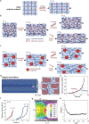
Figure 12.. Implementation of the design principle for tough hydrogels– build dissipation into stretchy polymer networks.
Schematics of the implementation strategies with a. interpenetrating or semiinterpenetrating polymer networks, b. polymer networks with high-functionality crosslinks, c. nano-/micro-fibrous polymer networks, and d. polymer networks with reversible crosslinks. e. nominal stress s-stretch λ relations for a PAAm-alginate hydrogel under loading and unloading. f. microscope image of the process zone around the crack in a PAMPS-PAAm hydrogel. g. microscope image of a fibrous fibrin hydrogel. e is adopted from Ref. f is adopted from Ref. g is adopted from Ref.
Figure 13.
Figure 13.. Design principle for strong hydrogels – synchronize stiffening and fracture of multiple polymer chains:
a. definition and measurement of the tensile strength. A and a are the cross-section areas of the sample in the undeformed and deformed states, and F is applied tensile force. b. the simultaneous stiffening and fracture of substantial polymer chains give a high tensile strength. Ff is the tensile force at the failure of the sample. c. the nominal tensile strength sc increases with the decrease of the defect size D up to a critical value Dc, below which the tensile strength is defect-insensitive,.
Figure 14.
Figure 14.. Implementation of the design principle for strong hydrogels – synchronize stiffening and fracture of multiple polymer chains.
Schematics on the implementation with a. polymer networks with high-functionality crosslinks, b. nano-/micro-fibrous polymer networks. c. confocal (left) and SEM (right) images of a fibrous PVA hydrogel with aligned fibers. d. nominal stress-stretch curves of the fibrous PVA hydrogels with aligned and randomly-oriented fibers. c and d are adopted from Ref.
Figure 15.
Figure 15.. Design principle for resilient and tough hydrogels – delay dissipation:
a. definition and measurement of resilience. The relation of nominal stress s and stretchλ of a sample is measured under uniaxial tension in a loading-unloading cycle. WR and WD are the energy released in the unloading and the dissipated energy per unit volume of the sample, respectively. The resilience can be calculated as R=WR/(WR+WD). b. when the stretch is below a critical stretch λR, the hydrogel releases most of the stored elastic energy during deformation recovery, giving high resilience; when the stretch is above λR, the hydrogel dissipates substantial mechanical energy, giving high fracture toughness. c. the stretch in the process zone around the crack is usually much higher than λR, dissipating substantial mechanical energy and giving high fracture toughness. b and c are adopted from Ref.
Figure 16.
Figure 16.. Implementation of the design principle for resilient and tough hydrogels – delay dissipation:
a. ideal polymer networks are resilient up to fracture due to the lack of dissipation mechanism. b. pre-stretching interpenetrating polymer networks to λR can make them both resilient and tough. c. prestretching polymer networks with high-functionality crosslinks to λR can make them both resilient and tough. d. nano-/micro-fibrous polymer networks with resilient fibers can be both resilient and tough. e. the nominal stress-stretch curve of a resilient and tough fibrous PVA hydrogels. f. the nominal stressstretch curves of a PAAm-alginate hydrogel with λR =5 . g. the measured strain field around a crack in the PAAm-alginate hydrogel with λR =5. h. the stretch in the process zone can be much higher than λR = 5 . e is adopted from Ref. f, g and h are adopted from Ref.
Figure 17.
Figure 17.. Design principle for tough adhesion of hydrogels – integrate tough dissipative hydrogels and strong interfacial linkages.
a. definition of interfacial toughness and the 90-degree peeling test to measure the interfacial toughness. F is the peeling force, Fplateau is the plateau peeling force, and W is the width of the sample. The interfacial toughness can be calculated as Γinter=Fplatenu/W based on the values of Fplateau and W measured in the 90-degree peeling test. b. weak interface can give the adhesive failure mode. c. brittle hydrogel matrix can give the cohesive failure mode. d. integration of tough dissipative hydrogels and strong interfacial linkages gives tough adhesion of hydrogels. The contributions of strong interfacial linkages and mechanical dissipation in the process zone to the total interfacial toughness are Γ0inter and ΓDinter, respectively. The total interfacial toughness of the tough adhesion is Γinter=Γ0inter+ΓDinter d is adopted from Ref.
Figure 18.
Figure 18.. Implementation of the design principle for tough adhesion of hydrogels – integrate tough hydrogels and strong interfacial linkages.
The tough UPNs are bonded on substrates via various types of strong interfacial linkages: a. covalent bonds, b. strong physical crosslinks, c. bridging polymers, and d. mechanical interlocks. e. catechol interactions can implement various types of strong interfacial linkages. e is adopted from Ref,.
Figure 19.
Figure 19.. Design principle for fatigue-resistant hydrogels – pin cracks by intrinsically high-energy phases.
a. definition of fatigue threshold and the pure-shear method to measure fatigue threshold. G is the energy release rate, c is the crack length, and N is the cycle number. The fatigue threshold ΓFT is determined by intersecting the curve of dc / dN vs G with the G axis. b. dissipation mechanisms such as reversible crosslinks in tough hydrogels are depleted over cyclic loads, not contributing to the fatigue threshold. c. fatigue crack is pinned by intrinsically high-energy phases in fatigue-resistant hydrogels. b and c are adopted from Ref.
Figure 20.
Figure 20.. Implementation of the design principle for fatigue-resistant hydrogels – pin cracks by intrinsically high-energy phases.
Fatigue cracks can be pinned by intrinsically high-energy phases including a. nano-crystalline domains, b. nano-/micro-fibers, c. micro-phase separations, d. macro-fibers. e. Molecular dynamic simulation of the energy for pulling a polymer chain out of a PVA nano-crystalline domain and for fracturing the same polymer chain. d is the displacement of one end of the polymer chain, and U is the energy required to achieve the displacement. f. confocal microscope image of a crack pinned by nano-fibers in a nano-fibrous PVA hydrogel, and g. measurement of the fatigue threshold of the nano-fibrous PVA hydrogel. G is the energy release rate, c is the crack length, and N is the cycle number. a is adopted from Ref, b is adopted from Ref, c is adopted from Ref, d is adopted from Ref, e is adopted from Ref, f and g are adopted from Ref.
Figure 21.
Figure 21.. Design principle for fatigue-resistant adhesion of hydrogels – strongly bond intrinsically high-energy phases on interfaces:
a. definition of interfacial fatigue threshold and the 90-degree cyclic peeling test to measure the interfacial fatigue threshold. F is the applied peeling force, W is the width of the sample, G is the energy release rate, c is the crack length, and N is the cycle number. The interfacial fatigue threshold ΓFTinter is determined by intersecting the curve of dc / dN vs G with the G axis. b. fatigue-crack propagation along the interface giving adhesive failure. c. fatigue-crack propagation in the hydrogel giving cohesive failure. d. fatigue-crack pinned by intrinsically high-energy phases on the interface and in the bulk hydrogel. d is adopted from Ref.
Figure 22.
Figure 22.. Implementation of the design principle for fatigue-resistant adhesion of hydrogels – strongly bond intrinsically high-energy phases on interfaces:
The intrinsically high-energy phases can be bonded on the substrates via a. high-density physical bonds such as hydrogen bonds, b. covalent bonds, and c. mechanical interlocks. d. measurements of the fatigue thresholds of tough adhesion and fatigueresistant adhesion of hydrogels on substrates. e. photos of interfacial crack propagation in a cyclic peeling test for tough adhesion (top) and fatigue-resistant adhesion (bottom) of hydrogels on substrates. a, d and e are adopted from Ref.
Figure 23.
Figure 23.. Design of hydrogels with high electrical conductivity – percolate electrically conductive phases.
a. hydrogels with percolated electrically conductive fillers. b. hydrogels with ionically conductive salt solvents. c. hydrogels based on conducting polymers. The bottom panel of a is adopted from Ref. The bottom panel of b is adopted from Ref. The bottom panels of c are adopted from Ref (left) and Ref (right).
Figure 24.
Figure 24.. Design of hydrogels and elastomers with patterned magnetization – embed magnetic particles and pattern ferromagnetic domains.
a. typical relations of applied magnetic field H and magnetization M for paramagnetic, soft-magnetic, and hard-magnetic materials. Mr and Hc are the residual magnetization and coercivity of the hard-magnetic material, respectively. b. hard-magnetic particles can be embedded into an elastomer/hydrogel matrix, in which ferromagnetic domains can be patterned by 3D printing. c. Photos of the resultant magnetic soft material before and after magnetic actuation. a is adopted from Ref. b and c are adopted from Ref.
Figure 25.
Figure 25.. Design of hydrogels with high reflective indices and transparency – uniformly embed high-refractive-index non-scattering nano-phases.
a. high contrast between reflective indices of the hydrogel fiber ηHF and tissue fluid ηTF can give minimal light leakage. b. uniformly embedding nano-phases such as nano-particles with high refractive indices in the hydrogel matrices can enhance the refractive index of the hydrogel. The size of the nano-phases dNC should be much smaller than the light wavelength λ for minimal scattering and high transparency. c. hydrogels with high reflective indices and transparency can be used as optical fibers in living tissues. d. photo of a hydrogel optical fiber. d is adopted from Ref.
Figure 26.
Figure 26.. Design of hydrogels with tunable acoustic impedance – tune densities and bulk moduli of effectively homogeneous hydrogels.
a. by infusing air, water or liquid metal (i.e., eutectic gallium-indium) into the fluidic channels inside a hydrogel matrix, the effective density, bulk modulus and thus acoustic impedance of the hydrogel can be dramatically varied. b. the hydrogel can approximate the acoustic impedance of air, water and many solids on demand. a and b are adopted from Ref.
Figure 27.
Figure 27.. Design of self-healing hydrogels – form crosslinks and/or polymers at damaged regions.
a. reversible crosslinks form on the interfaces between two pieces of hydrogels for self-healing or selfadhesion. b. damage of a hydrogel induces new polymerization and crosslinking, giving self-reinforcement or self-growth. c. photos of a self-healing hydrogel based on oppositely charged polyelectrolytes,. d. photos of a self-reinforcing or self-growing hydrogel. b and d are adopted from Ref. c is adopted from Ref.
Figure 28.
Figure 28.. Orthogonal design principles and synergistic implementation strategies for the design of hydrogels with multiple combined properties.
a. schematics of the orthogonal design principles and synergistic implementation strategies. b. example of the design of a tough, self-healing and electrically conductive hydrogel.

Similar articles

Cited by

References

    1. Wichterle O; LÍM D.Hydrophilic Gels for Biological Use. Nature 1960, 185 (4706), 117.
    1. Peppas NA; Bures P; Leobandung W; Ichikawa H.Hydrogels in pharmaceutical formulations. European Journal of Pharmaceutics and Biopharmaceutics 2000, 50 (1), 27. - PubMed
    1. Qiu Y; Park K.Environment-sensitive hydrogels for drug delivery. Advanced Drug Delivery Reviews 2001, 53 (3), 321. - PubMed
    1. Peppas NA; Hilt JZ; Khademhosseini A; Langer R.Hydrogels in Biology and Medicine: From Molecular Principles to Bionanotechnology. Advanced Materials 2006, 18 (11), 1345.
    1. Li J; Mooney DJ Designing hydrogels for controlled drug delivery. Nature Reviews Materials 2016, 1 (12), 16071. - PMC - PubMed

Publication types

LinkOut - more resources