

MR Imaging in the 21st Century: Technical Innovation over the First Two Decades
- PMID: 33867419
- PMCID: PMC9199974
- DOI: 10.2463/mrms.rev.2021-0011
MR Imaging in the 21st Century: Technical Innovation over the First Two Decades
Abstract
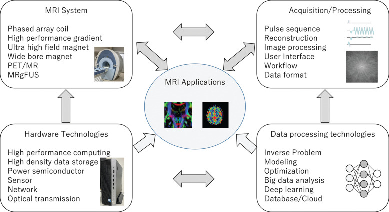
Clinical MRI systems have continually improved over the years since their introduction in the 1980s. In MRI technical development, the developments in each MRI system component, including data acquisition, image reconstruction, and hardware systems, have impacted the others. Progress in each component has induced new technology development opportunities in other components. New technologies outside of the MRI field, for example, computer science, data processing, and semiconductors, have been immediately incorporated into MRI development, which resulted in innovative applications. With high performance computing and MR technology innovations, MRI can now provide large volumes of functional and anatomical image datasets, which are important tools in various research fields. MRI systems are now combined with other modalities, such as positron emission tomography (PET) or therapeutic devices. These hybrid systems provide additional capabilities.In this review, MRI advances in the last two decades will be considered. We will discuss the progress of MRI systems, the enabling technology, established applications, current trends, and the future outlook.
Keywords: image acquisition; image reconstruction; magnetic resonance imaging; magnetic resonance imaging applications; magnetic resonance imaging system.
Conflict of interest statement
The author was an employee of GE Healthcare from April 1st, 1993 to March 31st, 2020. Most of the technical developments described in this review occurred during that period.
Figures
References
-
- Fukatsu H. 3T MR for clinical use: update. Magn Reson Med Sci 2003; 2:37–45. - PubMed
-
- Sasaki M, Inoue T, Tohyama K, et al. High-field MRI of the central nervous system: current approaches to clinical and microscopic imaging. Magn Reson Med Sci 2003; 2:133–139. - PubMed
-
- Naganawa S, Kawai H, Fukatsu H, et al. High-speed imaging at 3 Tesla: a technical and clinical review with an emphasis on whole-brain 3D imaging. Magn Reson Med Sci 2004; 3:177–187. - PubMed
-
- Uematsu H, Takahashi M, Dougherty L, et al. High field body MR imaging: preliminary experiences. Clin Imaging 2004; 28:159–162. - PubMed
-
- Kataoka M, Kido A, Koyama T, et al. MRI of the female pelvis at 3T compared to 1.5T: evaluation on high-resolution T2-weighted and HASTE images. J Magn Reson Imaging 2007; 25:527–534. - PubMed
Publication types
MeSH terms
LinkOut - more resources
Full Text Sources
Other Literature Sources
Medical