. 2021 Mar 18:8:649765.
doi: 10.3389/frobt.2021.649765. eCollection 2021.

Investigating Tissue Mechanics in vitro Using Untethered Soft Robotic Microdevices

Affiliations

Investigating Tissue Mechanics in vitro Using Untethered Soft Robotic Microdevices

Raquel Parreira et al. Front Robot AI. .

Abstract

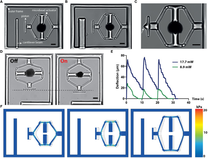
This paper presents the design, fabrication, and operation of a soft robotic compression device that is remotely powered by laser illumination. We combined the rapid and wireless response of hybrid nanomaterials with state-of-the-art microengineering techniques to develop machinery that can apply physiologically relevant mechanical loading. The passive hydrogel structures that constitute the compliant skeleton of the machines were fabricated using single-step in situ polymerization process and directly incorporated around the actuators without further assembly steps. Experimentally validated computational models guided the design of the compression mechanism. We incorporated a cantilever beam to the prototype for life-time monitoring of mechanical properties of cell clusters on optical microscopes. The mechanical and biochemical compatibility of the chosen materials with living cells together with the on-site manufacturing process enable seamless interfacing of soft robotic devices with biological specimen.

Keywords: 3D tissue constructs; hydrogels; mechanobiolgy; microfabrication; plasmonics; soft robotics.


Conflict of interest statement

The authors declare that the research was conducted in the absence of any commercial or financial relationships that could be construed as a potential conflict of interest.

Figures

Figure 1
Figure 1
Fabrication and operation of machine components. (A) Schematic illustration of the microfluidic colloidal assembly process. An aqueous solution of nOMAs and crosslinker forms the discontinuous phase while the continuous phase comprises the surfactant and oil mixture. The emulsion was collected and heated overnight to facilitate the crosslinking process. (B) A representative example showing the fully contracted state of a μOMA upon NIR illumination. The laser power on the sample was adjusted to 10 mW. Scale bar, 100 μm. (C) Actuation strain vs. time plot for a 15 mW NIR signal with 260 ms pulse duration at 0.8 Hz. (D) The fabrication methodology for building compliant flextensional mechanisms. The projector defines the geometry of the structures polymerizing around the actuators. (E) Snapshots from the actuation of a representative mechanism. Scale bar, 50 μm.
Figure 2
Figure 2
Design, operation, and computational analysis of the compressors. (A) A bright-field microscope image of the device showing different modules. (B) The cantilever beam geometry can be modified to tune the the sensitivity of the sensor. (C) The design of the piston can be modified to tune the applied stress. White arrow points to the sharp tip engineered for localized indentation. (D) Temporal sequence of micrographs from a representative actuation cycle. (E) The displacement vs. time plot for the piston at different NIR laser power. The signal duration is 500 ms and the actuation frequency is 0.1 Hz. (F) Simulation results for different flextensional mechanism designs. The arm angle and length can be modified to tune the piston displacement and stress on the mechanism. Scale bars, 100 μm.
Figure 3
Figure 3
Finite element simulations of the heat transfer during actuation. (A) 2D drawing showing the boundary conditions. Inset is a close-up view of the actuator highlighting the nanoheater elements. Scale bar, 10μm. (B) Temperature changes over a complete actuation cycle at the three different points shown in (A). The input excitation signal is shown on the bottom plot. (C) Temperature as a function of distance from the μOMA irradiated at 14.2 mW laser power at the steady state. Scale bar, 100 μm. (D) Selective actuation of a μOMA (denoted with the white arrow) at 14.2 mW laser power in close proximity of another μOMA. Bottom image shows that only the illuminated actuator responds to the signal. Scale bar, 100 μm.
Figure 4
Figure 4
Calibration of the sensing probe. (A) The position of the MEMS force sensor is controlled by a motorized 3-axis micromanipulator while the sample is translated on a plane using the microscope stage. (B) The base of the cantilever beams is polymerized directly around the PDMS micropillars using the digital maskless lithography system. The pillars stabilize the base and keep it stationary during mechanical loading. Scale bar, 100 μm. (C) Close-up of the cantilever beam and the tip of the sensor. Scale bar, 50 μm. (D) Snapshots from a representative indentation experiment. Scale bar, 50 μm. (E) A representative force vs. deflection curve. The slope of the linear fit is used for calculating the bending modulus. (F) Representative images from a compression test for PAAm beads. Scale bar, 100 μm.
Figure 5
Figure 5
Biomechanical characterization of 3D tissue samples. (A) Schematic depiction of the working principle (not to the scale). Upon application of NIR illumination, the monolithic compliant mechanism deforms and the piston compresses the sample. The cantilever beam reports the sample stiffness. (B) Phase-contrast image shows high-throughput fabrication of spheroids using hydrogel wells. (C) Fluorescent image of an array of self-assembled spheroids labeled with a DNA dye. (D) Snapshots from a representative compression experiment where the deflection of the beam is not obvious. (E) A compression device with a more sensitive cantilever beam. The beam deflects during the loading of the sample, reporting its stiffness. Scale bars, 100μm.

Similar articles

Cited by

  • Actuated 3D microgels for single cell mechanobiology.
    Özkale B, Lou J, Özelçi E, Elosegui-Artola A, Tringides CM, Mao AS, Sakar MS, Mooney DJ. Özkale B, et al. Lab Chip. 2022 May 17;22(10):1962-1970. doi: 10.1039/d2lc00203e. Lab Chip. 2022. PMID: 35437554 Free PMC article.

References

    1. Beebe D. J., Moore J. S., Bauer J. M., Yu Q., Liu R. H., Devadoss C., et al. . (2000). Functional hydrogel structures for autonomous flow control inside microfluidic channels. Nature 404, 588–590. 10.1038/35007047 - DOI - PubMed
    1. Beyeler F., Neild A., Oberti S., Bell D. J., Sun Y., Dual J., et al. . (2007). Monolithically fabricated microgripper with integrated force sensor for manipulating microobjects and biological cells aligned in an ultrasonic field. J. Microelectromech. Syst. 16, 7–15. 10.1109/JMEMS.2006.885853 - DOI
    1. Bhatia S. N., Ingber D. E. (2014). Microfluidic organs-on-chips. Nat. Biotechnol. 32:760. 10.1038/nbt.2989 - DOI - PubMed
    1. Brandenberg N., Hoehnel S., Kuttler F., Homicsko K., Ceroni C., Ringel T., et al. . (2020). High-throughput automated organoid culture via stem-cell aggregation in microcavity arrays. Nat. Biomed. Eng. 4, 1–12. 10.1038/s41551-020-0565-2 - DOI - PubMed
    1. Chung S. E., Park W., Park H., Yu K., Park N., Kwon S. (2007). Optofluidic maskless lithography system for real-time synthesis of photopolymerized microstructures in microfluidic channels. Appl. Phys. Lett. 91:041106. 10.1063/1.2759988 - DOI

LinkOut - more resources