. 2021 Aug;16(8):1255-1262.
doi: 10.1007/s11548-021-02366-5. Epub 2021 Apr 20.

Cryo-balloon catheter localization in X-Ray fluoroscopy using U-net

Affiliations

Cryo-balloon catheter localization in X-Ray fluoroscopy using U-net

Ina Vernikouskaya et al. Int J Comput Assist Radiol Surg. 2021 Aug.

Abstract

Purpose: Automatic identification of interventional devices in X-ray (XR) fluoroscopy offers the potential of improved navigation during transcatheter endovascular procedures. This paper presents a prototype implementation of fully automatic 3D reconstruction of a cryo-balloon catheter during pulmonary vein isolation (PVI) procedures by deep learning approaches.

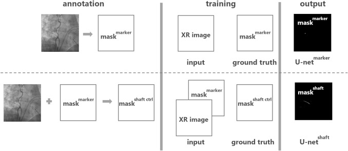
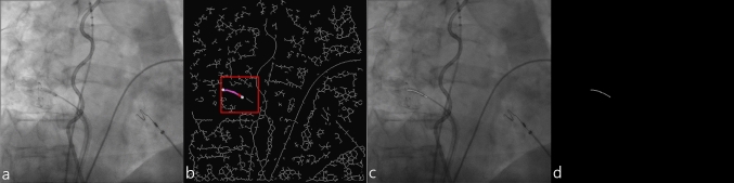
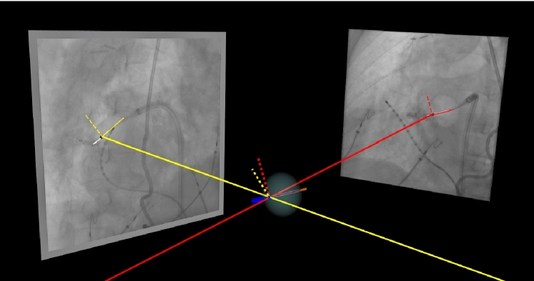
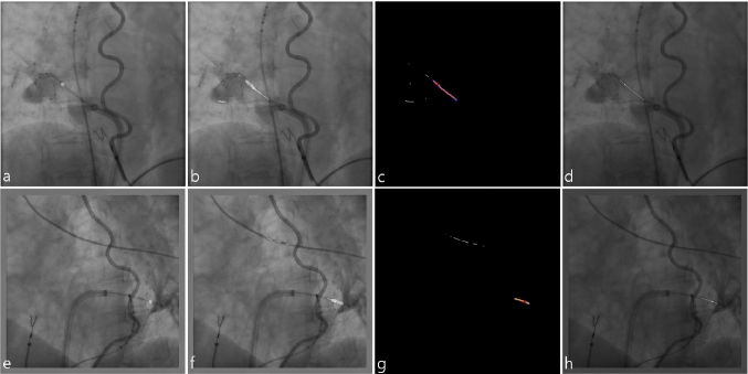
Methods: We employ convolutional neural networks (CNN) to automatically identify the cryo-balloon XR marker and catheter shaft in 2D fluoroscopy during PVI. Training data are generated exploiting established semiautomatic techniques, including template-matching and analytical graph building. A first network of U-net architecture uses a single grayscale XR image as input and yields the mask of the XR marker. A second network of the similar architecture is trained using the mask of the XR marker as additional input to the grayscale XR image for the segmentation of the cryo-balloon catheter shaft mask. The structures automatically identified in two 2D images with different angulations are then used to reconstruct the cryo-balloon in 3D.

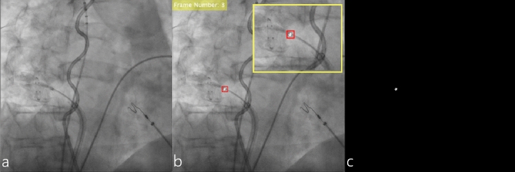
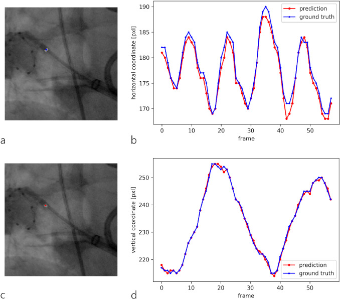
Results: Automatic identification of the XR marker was successful in 78% of test cases and in 100% for the catheter shaft. Training of the model for prediction of the XR marker mask was successful with 3426 training samples. Incorporation of the XR marker mask as additional input for the model predicting the catheter shaft allowed to achieve good training result with only 805 training samples. The average prediction time per frame was 14.47 ms for the XR marker and 78.22 ms for the catheter shaft. Localization accuracy for the XR marker yielded on average 1.52 pixels or 0.56 mm.

Conclusions: In this paper, we report a novel method for automatic detection and 3D reconstruction of the cryo-balloon catheter shaft and marker from 2D fluoroscopic images. Initial evaluation yields promising results thus indicating the high potential of CNNs as alternatives to the current state-of-the-art solutions.

Keywords: Automatic segmentation; Cryo-balloon; Reconstruction; Semi-automatic annotation; Unet.


Conflict of interest statement

The authors declare that they have no financial and personal relationships with other people or organizations that could inappropriately influence and/or bias this work.

Figures

Fig. 1
Fig. 1
Method processing algorithm subdivided into annotation, training, and output steps. Annotation step: the mask of the cryo-balloon marker maskmarker is obtained from the original XR image to be processed by the U-netmarker; the mask of the cryo-balloon catheter shaft centerline maskshaft ctrl is obtained from the original XR image and its corresponding maskmarker to be processed by the U-netshaft. Training step: U-netmarker is trained on the image sample consisting of original XR image and its corresponding maskmarker as ground truth; U-netshaft is trained on the image sample consisting of original XR image and its corresponding maskmarker as inputs and maskshaft ctrl as ground truth. Output step: maskmarker and maskshaft are predicted by the U-netmarker and U-netshaft correspondingly as images containing contours of specific pixel values against background
Fig. 2
Fig. 2
Semiautomatic annotation of the cryo-balloon marker: a original XR image; b XR frame with a rectangular template of 10 × 10 pixels set around the XR marker (red box) and overlaid thresholded pixels corresponding to the segmented marker (incl. close-up of the respective region of interest); c resulting binary mask maskmarker
Fig. 3
Fig. 3
Semiautomatic annotation of the cryo-balloon catheter shaft: a original XR image; b skeletonized binary image with the analytical graph (magenta) built within the 50 × 50 pixels ROI (red rectangular box) around the seed point (red point) and two end nodes (white points) indicating the longest path closest to the seed point and interpreted as a catheter shaft; c XR frame with overlaid resulting spline fitted longest path providing the centerline of the catheter shaft; d resulting binary mask maskshaft ctrl
Fig. 4.
Fig. 4.
3D reconstruction of the automatically detected seed points (black points in both XR images) and catheter shaft centerlines (white lines in both XR images) from frontal view acquired in RAO30° orientation (red lines) and lateral view acquired in LAO40° orientation (yellow lines) and alignment with the previously constructed 28 mm-sized cryo-balloon model. Solid red and yellow lines represent projection vectors for frontal and lateral views, respectively. Light red and yellow lines on both XR images represent respective line fitted centerlines. Dashed red and yellow lines on both XR images represent respective orthonormals, whereas dotted red and yellow lines represent transferred orthonormals initialized by the reconstructed 3D marker position aligned with the cryo-balloon model marker (dark blue small ellipsoid). Solid orange line represents resulting catheter orientation vector aligned with the cryo-balloon model shaft (dark blue line)
Fig. 5
Fig. 5
Evaluation of the XR marker prediction accuracy from test run 1: cutout of the annotated maskmarker (a) or predicted maskmarker (c) overlaid on original XR image with the colored point indicating the centroid of the annotated marker contour as ground truth (blue) or the centroid of the predicted contour (red); plot of the predicted centroid’s horizontal (b) and vertical (d) coordinates overlaid on the ground truth coordinates
Fig. 6
Fig. 6
Exemplary results of test run 1 (a–d) and test run 4 (e–h): a, e output of U-netmarker overlaid on original XR image; b, f output of U-netshaft overlaid on original XR image; c, g the post-processed binary image representing the skeleton of the image outputted by U-netshaft with the overlaid graph and a center of the contour detected by U-netmarker (red point); d, h resulting seed point and spline fitted centerline overlaid on original XR image
Fig. 7
Fig. 7
Projection of the constructed 28 mm-sized cryo-balloon model with ellipsoidal balloon (light blue) and catheter shaft (dark blue) with the tip (dark blue cylinder) and XR marker (dark blue small ellipsoid) onto RAO30° view acquired on the frontal C-arm (a) and LAO40° view acquired on the lateral C-arm (b). Automatically detected seed points are shown as black points in both XR images; catheter shaft centerlines are shown as white lines in both XR images

Similar articles

Cited by

References

    1. Kurzendorfer T, Mewes PW, Maier A, Strobel N, Brost A. Cryo-balloon catheter localization based on a support-vector-machine approach. IEEE Trans Med Imaging. 2016;35(8):1892–1902. doi: 10.1109/TMI.2016.2537052. - DOI - PubMed
    1. Bourier F, Fahrig R, Wang P, Santangeli P, Kurzidim K, Strobel N, Moore T, Hinkel C, Al-Ahmad A. Accuracy assessment of catheter guidance technology in electrophysiology procedures. J Cardiovasc Electrophysiol. 2014;25(1):74–83. doi: 10.1111/jce.12264. - DOI - PubMed
    1. Kowalewski CAB, Rodrigo M, Brodt C, Haddad F, Wang PJ, Narayan SM. Novel three-dimensional imaging approach for cryoballoon navigation and confirmation of pulmonary vein occlusion. Pacing Clin Electrophysiol PACE. 2020;43(3):269–277. doi: 10.1111/pace.13858. - DOI - PMC - PubMed
    1. Hoffmann M, Brost A, Jakob C, Bourier F, Koch M, Kurzidim K, Hornegger J, Strobel N (2012) Semi-automatic catheter reconstruction from two views. MICCAI 2012. Lecture Notes in Computer Science. pp 584–591 - PubMed
    1. Bourier F, Brost A, Kleinoeder A, Kurzendorfer T, Koch M, Kiraly A, Schneider HJ, Hornegger J, Strobel N, Kurzidim K. Navigation for fluoroscopy-guided cryo-balloon ablation procedures of atrial fibrillation. Proc SPIE Med Imaging. 2012;2012:8316.