. 2021 Jul 18;23(7):983-1008.
doi: 10.1093/europace/euaa367.

EHRA expert consensus statement and practical guide on optimal implantation technique for conventional pacemakers and implantable cardioverter-defibrillators: endorsed by the Heart Rhythm Society (HRS), the Asia Pacific Heart Rhythm Society (APHRS), and the Latin-American Heart Rhythm Society (LAHRS)

Affiliations

EHRA expert consensus statement and practical guide on optimal implantation technique for conventional pacemakers and implantable cardioverter-defibrillators: endorsed by the Heart Rhythm Society (HRS), the Asia Pacific Heart Rhythm Society (APHRS), and the Latin-American Heart Rhythm Society (LAHRS)

Haran Burri et al. Europace. .

Abstract

With the global increase in device implantations, there is a growing need to train physicians to implant pacemakers and implantable cardioverter-defibrillators. Although there are international recommendations for device indications and programming, there is no consensus to date regarding implantation technique. This document is founded on a systematic literature search and review, and on consensus from an international task force. It aims to fill the gap by setting standards for device implantation.

Keywords: Consensus document; Implantable cardioverter-defibrillator; Implantation; Pacemaker; Recommendations.


Figures

Figure 1
Figure 1
Cephalic venous cutdown (right-sided). (A) Dissection to the deltopectoral groove, with exposure of the cephalic vein to which are looped a proximal (top) and distal tie (bottom). The distal tie is fastened and gently pulled with a clamp. The anterior part of the vein is lifted by forceps and a venotomy made with a scalpel or scissors to expose the lumen of the vein (a common mistake is to incise only to the adventitia). Alternatively, the vein may be punctured with a needle or venous catheter to introduce a guidewire. (B) The vein lifter (yellow tool) is used to introduce the lead (alternatively a guidewire can be inserted to use a sheath). If blood prevents visualization of the lumen, the proximal tie can be pulled gently to prevent backflow and then released once the lead is inserted.
Figure 2
Figure 2
Lead crush with subclavian vein puncture. Patient with a single chamber pacemaker who had lead failure due to subclavian crush (arrow). An additional lead was implanted by axillary vein puncture.
Figure 3
Figure 3
Axillary vein puncture using fluoroscopic landmarks. The caudal tilt exposes the outer margin of the lung, allowing safe puncture and minimizing risk of pneumothorax. The target site is shown in the rectangle (top right). After successful puncture, a guidewire is inserted and the needle entry site in the vein can be appreciated (bottom right).
Figure 4
Figure 4
Unintentional cannulation of the azygous vein by the J-wire, with the pacing lead in the superior vena cava/right atrium for comparison. Note the course of the J-wire above the right main bronchus shown by the dotted lines in the postero-anteior (PA) view, which plunges posteriorly in the left anterior oblique (LAO) view.
Figure 5
Figure 5
Persistent left superior vena cava. (A) Single left superior vena cava (absent right superior vena cava) draining into a severely dilated coronary sinus. (B) Persistent left superior vena cava in a patient with a coexistent right vena cava (without a bridging innominate vein) and smaller size of the coronary sinus. (C) Same patient as A with a dual chamber pacemaker (PA view). Note the lead course leftward of the spine, and the alpha loop of the right ventricular lead. (D) Same patient as A (left lateral view). Note the posterior course of both leads within the coronary sinus.
Figure 6
Figure 6
Anatomy of the heart chambers relevant for pacing. (Left) Right anterior oblique view (∼20°) of the heart. Note proximity of the tip (*) of the right atrial appendage (RAA) to the aortic root (Ao) and the right ventricle. The target site for right atrial lead implantation is shaded (grey circle). (Middle) Right anterior oblique view (∼20°) of the heart after dissection of the anterior wall of the right heart chambers. The pacing lead is positioned on the mid-septum against the septo-marginal trabeculation (SMT) below the supraventricular crest (SVcrest), which forms the inferior border of the right ventricular outflow tract (RVOT). A noticeable «jump» can be seen as the lead is pulled back from the RVOT over these structures. (Right) Right anterior oblique view (∼30°) of the dissected transilluminated heart. Note how thin the right atrial appendage (RAA) wall is between pectinate muscles. The tricuspid valve leaflets have been excised to expose the membranous septum (MS), and their hinge points are represented by the dotted line. Approximate location of the atrioventricular node (AVN) and course of the His bundle and right bundle branch (RBB) are shown. Other abbreviations: BB, Bachmann’s bundle region; CS, coronary sinus; FO, fossa ovalis; PA, pulmonary artery; RVA, right ventricular apex; SVC, superior vena cava; TV, anterior leaflet of tricuspid valve. Images courtesy of Maxim Didenko, MD, PhD.
Figure 7
Figure 7
Lead position in the right ventricular apex. Note how the apical position is more apparent in the right anterior oblique (RAO) 30° view than in the postero-anterior (PA) view. The left anterior oblique (LAO) view allows to rule out placement of the lead in the left ventricle via a septal defect or in a tributary of the coronary sinus (e.g. in a posterior vein). Images modified from a virtual reality simulator used for training device implantation, with anatomy reconstructed from patient CT scans.
Figure 8
Figure 8
Fluoroscopic landmarks for right ventricular mid-septal lead positioning. The lead is implanted in the antero-septal groove and masquerades as a septal position in the left anterior oblique (LAO) 40–60° and postero-anterior (PA) views. The Right anterior oblique (RAO) 20–30°view shows that the lead is in fact anterior. A 3 × 3 grid can be drawn from the lateral border of the spinal column to the apex in the RAO 20–30°view, targeting the middle square. Dilatation or hypertrophy of the left ventricle may however modify the cardiac silhouette and the landmark. Images modified from Burri et al.
Figure 9
Figure 9
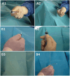
Shaping of stylets for ventricular lead positioning. (A) Shaping of a 2D stylet. Use of the barrel of a 10 mL syringe (smaller syringes may also be used) for entering the right ventricle (apical or septal positioning). (B1–4) Shaping of a 3D stylet. Use of a 5 mL syringe to shape a distal sharp posterior curve, followed by a larger proximal curve using a 10 mL syringe (the nozzle of this syringe may also be used for the distal curve). The stylets may also be shaped using a metalic tool with a compress or the fingers. Reproduced from Burri et al.
Figure 10
Figure 10
Recordings from the pacing system analyser at implantation. Increase in current of injury before (left) and after (right) helix deployment. Top: atrial (A) lead (note absence of a far-field R-wave). Bottom: Ventricular (V) lead.
Figure 11
Figure 11
Anchor knot for securing the lead. A non-resorbable braided suture (1, 0 or 1–0) with a large curved needle should be used. Left: The lead and muscle should not be taken together for suturing the sleeve to the muscle, as tissue may necrose and shrink, resulting in loosening of the tie. Right: An anchor non-slip knot should be place on the muscle and then sutured to the sleeve. At least one addition suture should be placed, either in the same manner, or simply around the sleeve so as to further secure the lead.
Figure 12
Figure 12
Closure of the pocket. Left: The leads are wrapped around and under the generator, care being taken to avoid kinks. The header is oriented towards the incision (adjacent to the deltopectoral groove in this case). Right: The pocket is closed by tying down the fascia to the muscle by separate stitches (resorbable braided suture) to imprison the generator and the leads in the pocket. The subcutaneous and epidermal layers are then sutured separately (dotted lines).
Figure 13
Figure 13
Compressive bandage to avoid haematoma. The roll and tape are placed immediately after the dressing is applied, and left until the following day.

References

    1. Raatikainen MJP, Arnar DO, Merkely B, Nielsen JC, Hindricks G, Heidbuchel H et al. A decade of information on the use of cardiac implantable electronic devices and interventional electrophysiological procedures in the European Society of Cardiology Countries: 2017 report from the European Heart Rhythm Association. Europace 2017;19:ii1–90. - PubMed
    1. Curtis JP, Luebbert JJ, Wang Y, Rathore SS, Chen J, Heidenreich PA et al. Association of physician certification and outcomes among patients receiving an implantable cardioverter-defibrillator. JAMA 2009;301:1661–70. - PMC - PubMed
    1. Cheng A, Wang Y, Curtis JP, Varosy PD. Acute lead dislodgements and in-hospital mortality in patients enrolled in the national cardiovascular data registry implantable cardioverter defibrillator registry. J Am Coll Cardiol 2010;56:1651–6. - PubMed
    1. Chui PW, Wang Y, Ranasinghe I, Mitiku TY, Seto AH, Rosman L et al. Association of physician specialty with long-term implantable cardioverter-defibrillator complication and reoperations rates. Circ Cardiovasc Qual Outcomes 2019;12:e005374. - PMC - PubMed
    1. Merino JL, Arribas F, Botto GL, Huikuri H, Kraemer LI, Linde C et al. ; on behalf of the 2005-2007 Accreditation Committee; European Heart Rhythm Association; European Society of Cardiology. Core curriculum for the heart rhythm specialist: executive summary. Europace 2009;11:1381–6. - PubMed