

Ultrasound-Guided Wireless Tubular Robotic Anchoring System
- PMID: 33880401
- PMCID: PMC7610639
- DOI: 10.1109/LRA.2020.3003868
Ultrasound-Guided Wireless Tubular Robotic Anchoring System
Abstract
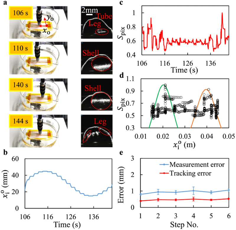
Untethered miniature robots have significant poten-tial and promise in diverse minimally invasive medical applications inside the human body. For drug delivery and physical contra-ception applications inside tubular structures, it is desirable to have a miniature anchoring robot with self-locking mechanism at a target tubular region. Moreover, the behavior of this robot should be tracked and feedback-controlled by a medical imaging-based system. While such a system is unavailable, we report a reversible untethered anchoring robot design based on remote magnetic actuation. The current robot prototype's dimension is 7.5 mm in diameter, 17.8 mm in length, and made of soft polyurethane elastomer, photopolymer, and two tiny permanent magnets. Its relaxation and anchoring states can be maintained in a stable manner without supplying any control and actuation input. To control the robot's locomotion, we implement a two-dimensional (2D) ultrasound imaging-based tracking and control system, which automatically sweeps locally and updates the robot's position. With such a system, we demonstrate that the robot can be controlled to follow a pre-defined 1D path with the maximal position error of 0.53 ± 0.05 mm inside a tubular phantom, where the reversible anchoring could be achieved under the monitoring of ultrasound imaging.
Keywords: Medical robots and systems; computer vision for medical robotics; mechanism design; soft robotics; ultrasound imaging-based control.
Figures


Similar articles
-
On-demand anchoring of wireless soft miniature robots on soft surfaces.Proc Natl Acad Sci U S A. 2022 Aug 23;119(34):e2207767119. doi: 10.1073/pnas.2207767119. Epub 2022 Aug 15. Proc Natl Acad Sci U S A. 2022. PMID: 35969749 Free PMC article.
-
Real-Time Ultrasound Doppler Tracking and Autonomous Navigation of a Miniature Helical Robot for Accelerating Thrombolysis in Dynamic Blood Flow.ACS Nano. 2022 Jan 25;16(1):604-616. doi: 10.1021/acsnano.1c07830. Epub 2022 Jan 4. ACS Nano. 2022. PMID: 34985859
-
Wireless MRI-Powered Reversible Orientation-Locking Capsule Robot.Adv Sci (Weinh). 2021 Jul;8(13):2100463. doi: 10.1002/advs.202100463. Epub 2021 May 3. Adv Sci (Weinh). 2021. PMID: 35478933 Free PMC article.
-
Actuation and design innovations in earthworm-inspired soft robots: A review.Front Bioeng Biotechnol. 2023 Feb 21;11:1088105. doi: 10.3389/fbioe.2023.1088105. eCollection 2023. Front Bioeng Biotechnol. 2023. PMID: 36896011 Free PMC article. Review.
-
Medical capsule robots: A renaissance for diagnostics, drug delivery and surgical treatment.J Control Release. 2017 Sep 10;261:337-351. doi: 10.1016/j.jconrel.2017.07.005. Epub 2017 Jul 8. J Control Release. 2017. PMID: 28694029 Review.
Cited by
-
Design and build of small-scale magnetic soft-bodied robots with multimodal locomotion.Nat Protoc. 2024 Feb;19(2):441-486. doi: 10.1038/s41596-023-00916-6. Epub 2023 Dec 14. Nat Protoc. 2024. PMID: 38097687 Review.
-
Adaptive wireless millirobotic locomotion into distal vasculature.Nat Commun. 2022 Aug 1;13(1):4465. doi: 10.1038/s41467-022-32059-9. Nat Commun. 2022. PMID: 35915075 Free PMC article.
-
Evolving from Laboratory Toys towards Life-Savers: Small-Scale Magnetic Robotic Systems with Medical Imaging Modalities.Micromachines (Basel). 2021 Oct 26;12(11):1310. doi: 10.3390/mi12111310. Micromachines (Basel). 2021. PMID: 34832722 Free PMC article. Review.
-
Untethered shape-changing devices in the gastrointestinal tract.Expert Opin Drug Deliv. 2023 Jul-Dec;20(12):1801-1822. doi: 10.1080/17425247.2023.2291450. Epub 2023 Dec 29. Expert Opin Drug Deliv. 2023. PMID: 38044866 Free PMC article. Review.
References
-
- Sitti M. Miniature soft robotsroad to the clinic. Nature Rev Mater. 2018;3(6):74.
-
- Sitti M. Mobile Microrobotics. MIT Press; Cambridge, MA, USA: 2017.
-
- Nelson BJ, Kaliakatsos IK, Abbott JJ. Microrobots for minimally invasive medicine. Annu Rev Biomed Eng. 2010;12:55–85. - PubMed
-
- Sitti M. Miniature devices: Voyage of the microrobots. Nature. 2009;458(7242):1121–1122. - PubMed
Grants and funding
LinkOut - more resources
Full Text Sources
Other Literature Sources