. 2021 Apr 23;12(1):2399.
doi: 10.1038/s41467-021-22663-6.

Imperceptible energy harvesting device and biomedical sensor based on ultraflexible ferroelectric transducers and organic diodes

Affiliations

Imperceptible energy harvesting device and biomedical sensor based on ultraflexible ferroelectric transducers and organic diodes

Andreas Petritz et al. Nat Commun. .

Abstract

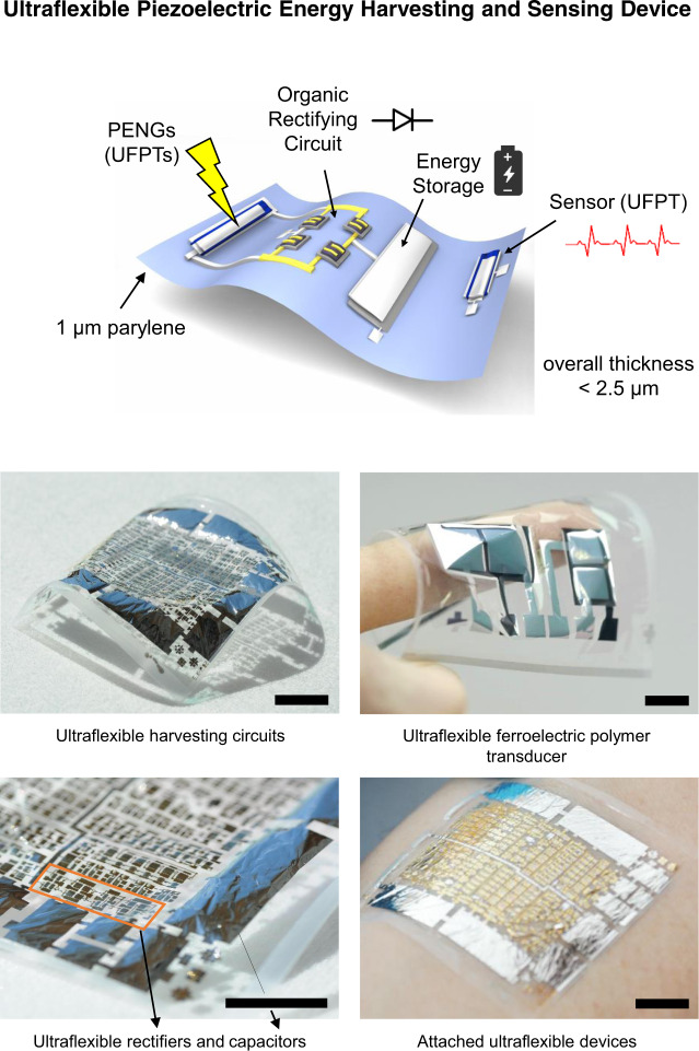
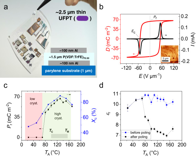
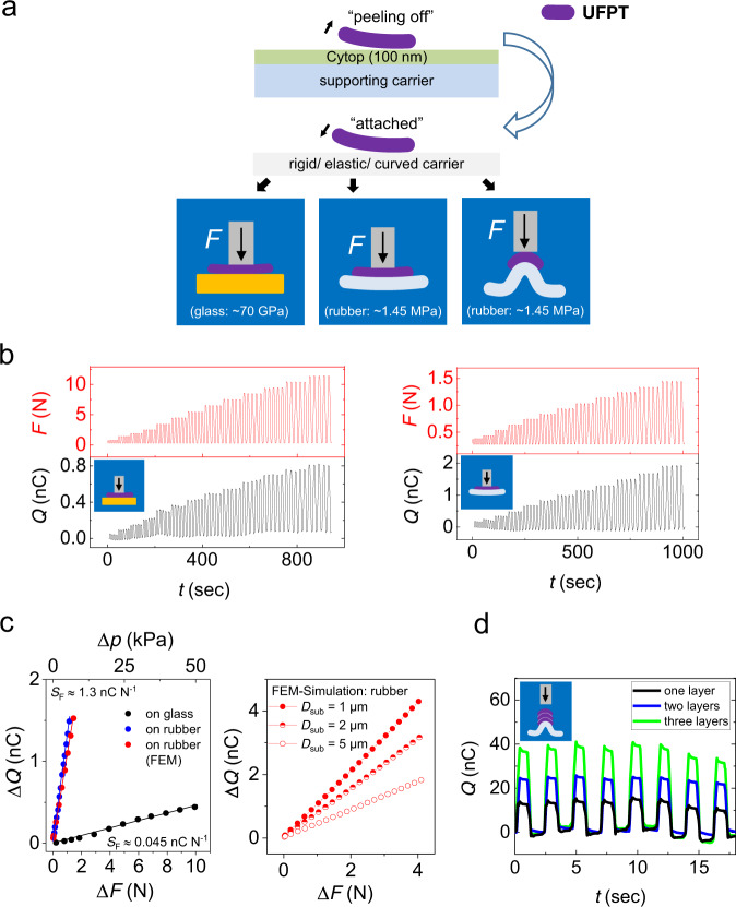
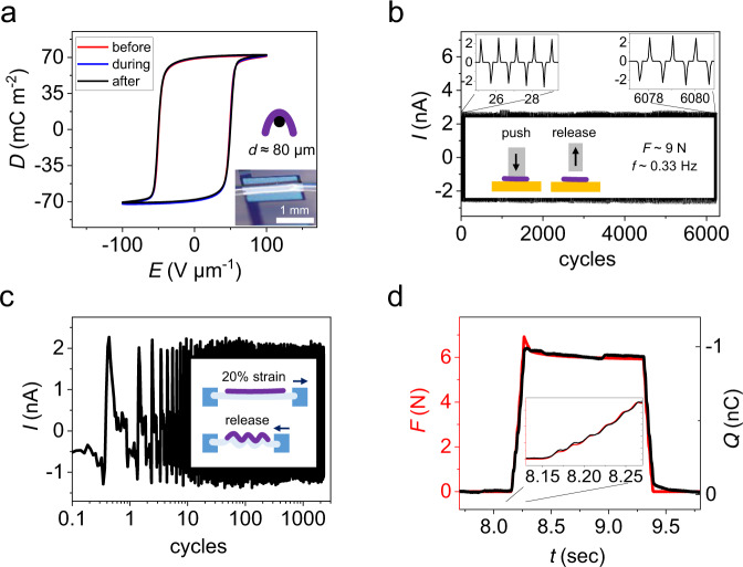
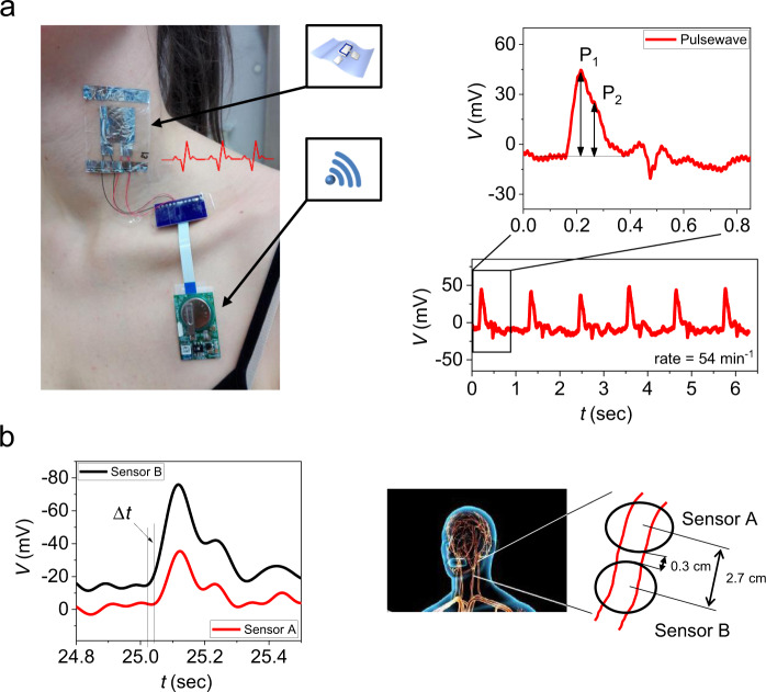
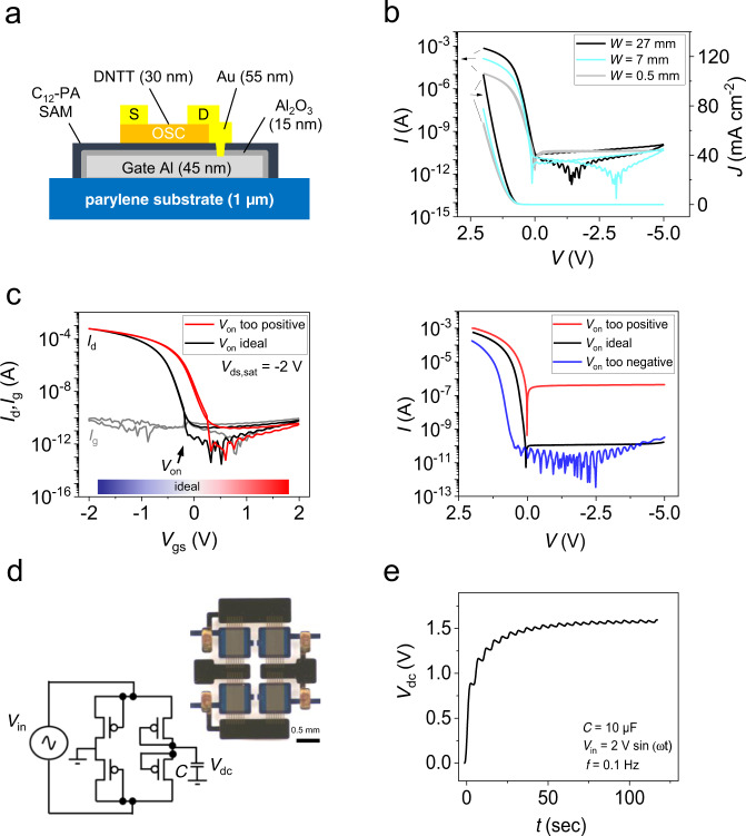
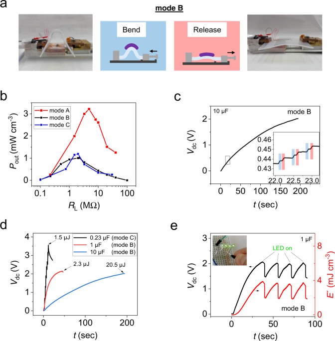
Energy autonomy and conformability are essential elements in the next generation of wearable and flexible electronics for healthcare, robotics and cyber-physical systems. This study presents ferroelectric polymer transducers and organic diodes for imperceptible sensing and energy harvesting systems, which are integrated on ultrathin (1-µm) substrates, thus imparting them with excellent flexibility. Simulations show that the sensitivity of ultraflexible ferroelectric polymer transducers is strongly enhanced by using an ultrathin substrate, which allows the mounting on 3D-shaped objects and the stacking in multiple layers. Indeed, ultraflexible ferroelectric polymer transducers have improved sensitivity to strain and pressure, fast response and excellent mechanical stability, thus forming imperceptible wireless e-health patches for precise pulse and blood pressure monitoring. For harvesting biomechanical energy, the transducers are combined with rectifiers based on ultraflexible organic diodes thus comprising an imperceptible, 2.5-µm thin, energy harvesting device with an excellent peak power density of 3 mW·cm-3.


Conflict of interest statement

The authors declare no competing interests.

Figures

Fig. 1
Fig. 1. Ultraflexible piezoelectric energy harvesting and sensing.
Scheme of a range of ultraflexible devices integrated on a 1-µm thin parylene substrate and photographs of the fabricated devices. Ultraflexible ferroelectric polymer transducers (UFPTs) are used for vital parameter sensing and as piezoelectric nanogenerators (PENGs) for harvesting biomechanical energy when attached to the skin. For the comprehensive ultraflexible energy-harvesting device (UEHD), the ultraflexible nanogenerators are combined with ultraflexible circuits comprising organic diodes as rectifiers and thin-film capacitors for energy storage. Scale bar, 1 cm.
Fig. 2
Fig. 2. Ultraflexible ferroelectric polymer transducer (UFPT) setup, and the ferroelectric and dielectric properties.
a Photograph of the ultraflexible P(VDF:TrFE)70:30-based transducer with a 1-µm thin diX-SR (parylene) substrate and the illustration of its setup. b Representative D(E) hysteresis curve of the ferroelectric layer measured during poling at 1 Hz after annealing at 130 °C. Ec denotes the coercive electric field strength where most microscopic dipoles start to rearrange themselves under the presence of an applied external field, and Pr is the remnant polarisation in the absence of an external field (i.e., D(E = 0 V µm−1)), which is the main figure-of-merit for the transducer. c Pr and degree of crystallinity Xc as a function of the annealing temperature TA. The melting point (TM) was reported earlier to be 153 °C and the Curie temperature TC was measured to be ~ 105 °C (see Supplementary Fig. 2). d The dependence of εr (mean value) on TA measured before and after poling. The displayed values of Pr and εr for each TA in (c) and (d) are mean values with standard deviations determined from at least ten devices with layer thickness values between 1.3 and 1.5 µm.
Fig. 3
Fig. 3. Transversal-load test on different carrier substrates.
a During fabrication, UFPT films are fixed on a supporting glass carrier. Later, the UFPT films can be easily peeled off the supporting glass carrier and applied to various carriers with different structure, shapes, curvatures or material mechanic properties. To perform transversal-load testing, the UFPTs were applied to one of two types of carriers: a 1-mm-thick rigid flat glass carrier (Young modulus Y ~70 GPa) or a 6-mm-thick elastic silicone rubber carrier (Y ~1.45 MPa). A stamp attached to a piston exerted a periodic step-like transversal force F onto the UFPTs in three different setups, namely, for the rigid flat glass carrier and for the elastic silicone rubber carrier in flat or in pre-bent curved shape, which resulted in three different excitation schemes. b The charge response of a single transducer layer attached to the flat glass carrier for transversal peak loads ranging between 0.25 N and 10.25 N (left) and to the flat silicone rubber carrier for peak transversal loads ranging between 0.25 N and 1.25 N (right). The small baseline fluctuation is stemming from charges generated by thermal fluctuations. c The charge response of the transducer for glass and silicone rubber carriers from (b), plotted as a function of the applied force and pressure differences ΔF and Δp, respectively. From the strictly linear relation ΔQF) (and also ΔQp)), a sensitivity value SF can extract as the slope of the regression line (generated by linear least square fits). The results of the FEM simulations of the charge response to transversal loading for UFPTs with three different parylene substrate thicknesses Dsub on rubber carriers are shown on the right. d Charge response of one, two and three piezoelectric transducer layers attached to a pre-bent (curved) rubber carrier under repetitive transversal loading of ΔF = 2.5 N.
Fig. 4
Fig. 4. Stability test and response time measurements of UFPTs.
a D(E)-hysteresis curve of an UFPT before, during and after bending over an 80-µm-thick gold wire. Durability testing under (b) transversal-load and (c) longitudinal-strain conditions. b Current response when a transducer mounted on a glass carrier is subjected to repeated transversal compression and release via a stamp over a period of more than 5 h (>6000 cycles). c Current response upon longitudinal strain cycling over more than 1000 periods. The inset schematically illustrates the longitudinal tensile test procedure. First, the UFPT was mounted on a 20% pre-strained rubber carrier, which was clamped at both ends. Then, by periodically relaxing and stretching the carrier (light blue) over an interval of 0–20% strain, the transducer (purple) was contracted or retracted, respectively. d Time dependence of the charge response of the UFPT for a trapezoidal transversal load with a top force level of 6 N and a rise time of « 20 ms N−1. The charge response signal (black) precisely follows the force profile (red).
Fig. 5
Fig. 5. Wireless e-health patch.
Attachment points of the wireless e-health patch, whereby the ultraflexible transducer serves as an imperceptible sensor that adheres to the skin without adhesive. The patch can monitor (a) the human pulse wave (with P1 and P2 peaks) from which the rate (here: 54 min−1 for a 32-year-old woman) and the artery augmentation index AI (here: AI ~56%) can be measured as well as (b) the blood pressure of the human arteria in the neck via the pulse wave velocity PWV. PWV can be determined by measuring the signal delay Δt for a given sensor distance Δx. In this example, PWV was ~9 m s−1 for a 34-year-old man.
Fig. 6
Fig. 6. Ultraflexible organic rectifier circuit.
a Scheme of the organic rectifier diode created with an OTFT by shortening the drain and gate contacts (C12-PA = 12-dodecylphosphonic acid, OSC = organic semiconductor, S = source and D = drain). b Representative I/V (J/V) curves of the organic diode for different channel widths W (channel length L fixed to 12 µm) fabricated on 1-µm thin parylene. J is the current density. c The electrical transfer characteristics of the OTFT (left plot) are related to its performance when used as a diode (right plot) by shortening the drain-gate contacts. The characteristics in the left plot correspond to the black and red graph (‘Von ideal’ and ‘Von too positive’) in the right plot (see main text). d Photograph and equivalent circuit of an OTFT-based full-wave rectifier circuit (OFWR) with W/L = 7000 µm/12 µm fabricated on 1-µm thin parylene. e Rectified output signal from an OFWR fed by an AC input signal Vin (2 V sin (2πft), f = 0.1 Hz) and connected to a capacitor of C = 10 µF.
Fig. 7
Fig. 7. Energy harvesting.
Harvesting of actuation energy generated by periodic (2 Hz) bending and releasing of an UFPT placed on top of a 2-mm-thick rubber layer via sliding on a rail (mode B). a Photographs and schematics of the bending procedure. b The output power density Pout of mode B is plotted as a function of load resistance RL (black curve) and compared to those from mode A (red curve) and mode C (blue curve). c Charging curve of a capacitor for an UFPT excited in mode B. The UFPT is connected to the ultrathin OFWR, which then charges the capacitor (C = 10 µF). The enlargement shows the generated energy steps related to bending (blue) and releasing (red) motions. d The capacitor voltages Vdc plotted over time and the maximum stored energy levels (E=12CVdc2) are shown for three different capacitor values, whereby the smallest capacitor with 0.23 µF is an ultraflexible thin-film capacitor fabricated on the 1-µm thin parylene substrate. For charging the thin-film capacitor, the UFPT was excited by bending mode C. Capacitors were charged almost to saturation. The maximum charging voltage depends on the generated energy of the PENGs (voltage levels), discharging effects and parasitic voltage drops along the energy harvesting circuits. e The time dependence of capacitor voltage Vdc and of the energy density E’ generated by periodically bending an UFPT and dissipating the energy by powering four LEDs that are connected in parallel.

References

    1. Stadlober B, Zirkl M, Irimia-Vladu M. Route towards sustainable smart sensors: ferroelectric polyvinylidene fluoride-based materials and their integration in flexible electronics. Chem. Soc. Rev. 2019;48:1787–1825. doi: 10.1039/C8CS00928G. - DOI - PubMed
    1. Myny K. The development of flexible integrated circuits based on thin-film transistors. Nat. Electron. 2018;1:30–39. doi: 10.1038/s41928-017-0008-6. - DOI
    1. Matsui H, Takeda Y, Tokito S. Flexible and printed organic transistors: from materials to integrated circuits. Org. Electron. 2019;75:105432. doi: 10.1016/j.orgel.2019.105432. - DOI
    1. García Núñez C, Manjakkal L, Dahiya R. Energy autonomous electronic skin. npj Flex. Electron. 2019;3:1. doi: 10.1038/s41528-018-0045-x. - DOI
    1. Hammock ML, Chortos A, Tee BC-K, Tok JB-H, Bao Z. 25th Anniversary Article: the evolution of electronic skin (E-Skin): a brief history, design considerations, and recent progress. Adv. Mater. 2013;25:5997–6038. doi: 10.1002/adma.201302240. - DOI - PubMed

Publication types

MeSH terms