Review
. 2021 May 12;121(9):5479-5596.
doi: 10.1021/acs.chemrev.1c00055. Epub 2021 Apr 28.

Structure, Assembly, and Function of Tripartite Efflux and Type 1 Secretion Systems in Gram-Negative Bacteria

Affiliations
Review

Structure, Assembly, and Function of Tripartite Efflux and Type 1 Secretion Systems in Gram-Negative Bacteria

Ilyas Alav et al. Chem Rev. .

Abstract

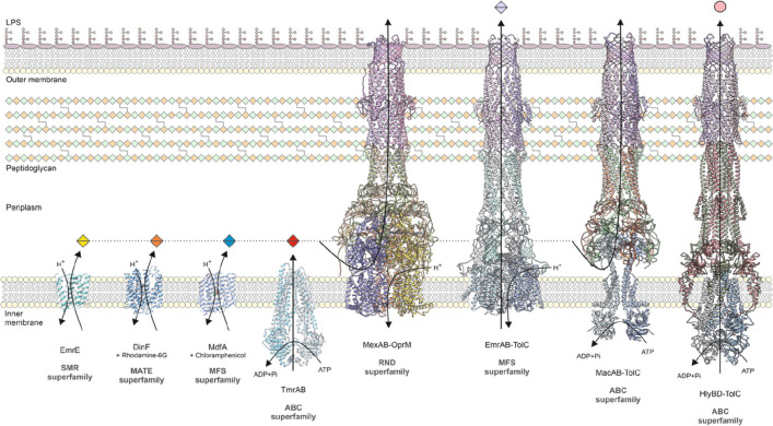
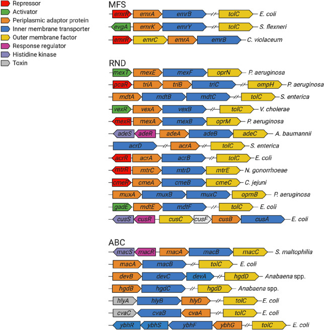
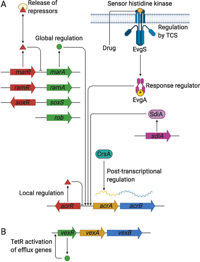
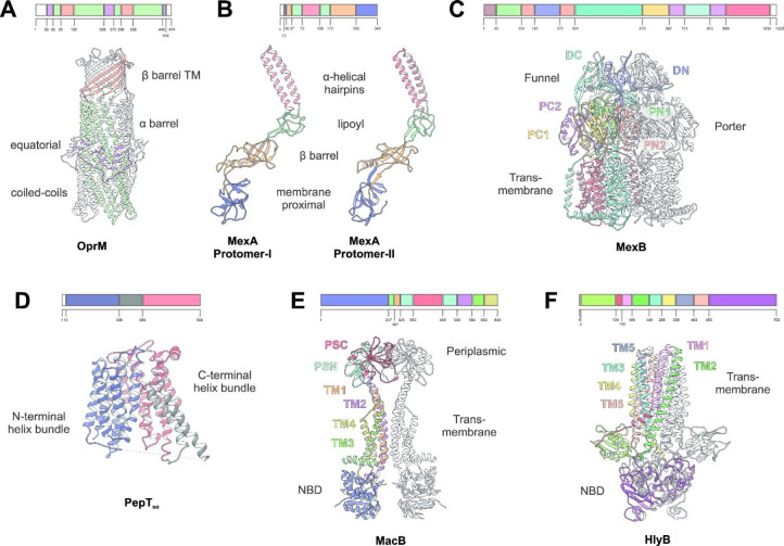
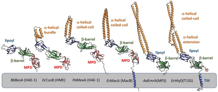
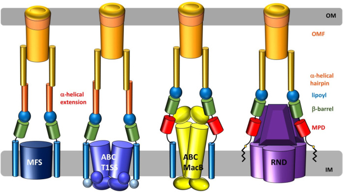
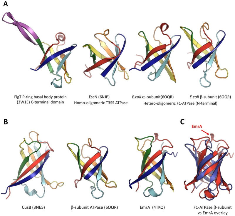
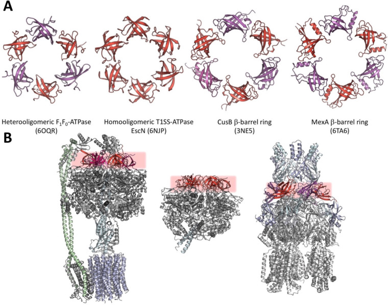
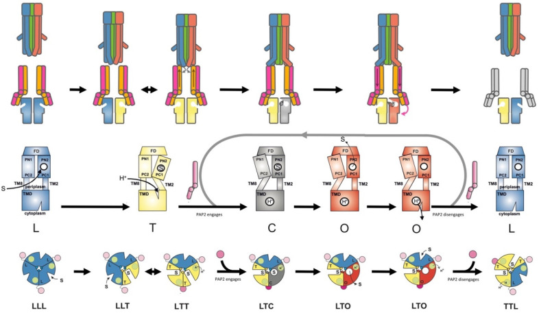
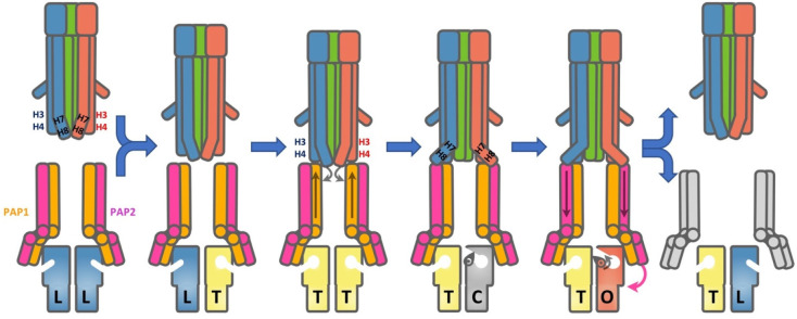
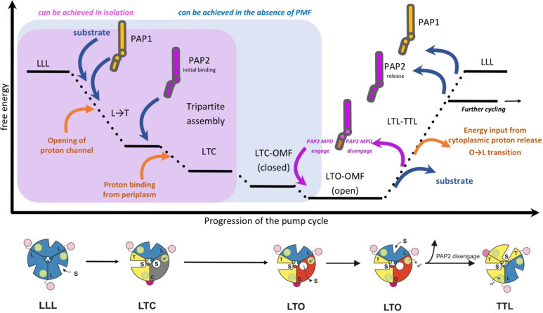
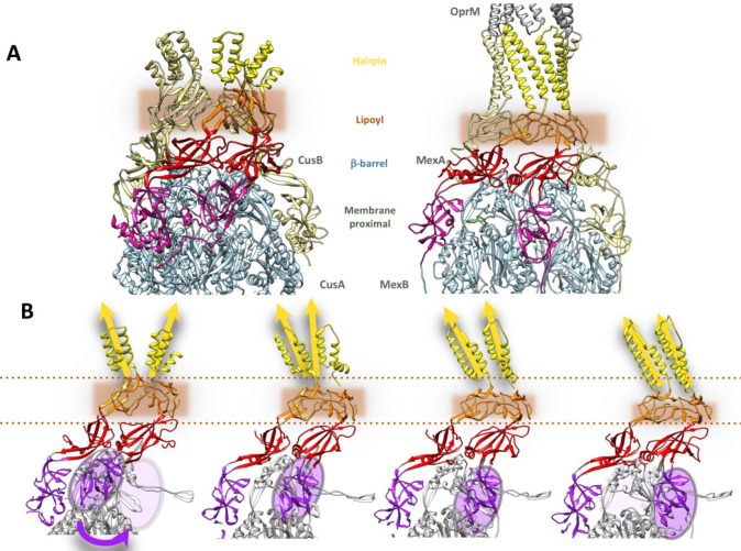
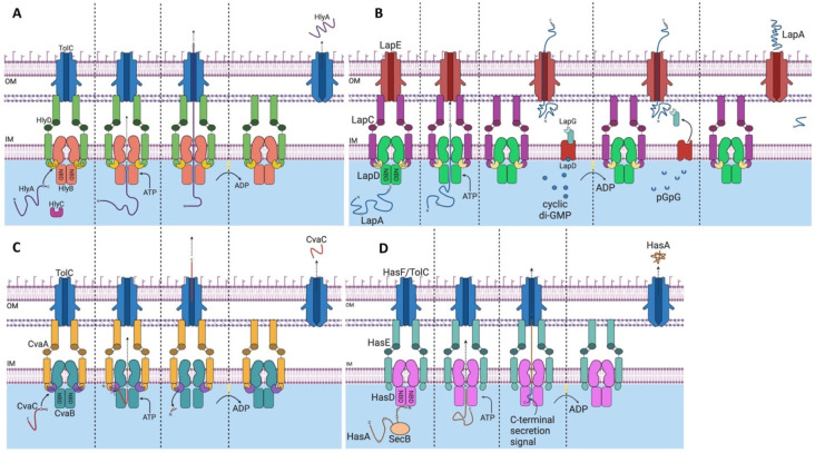
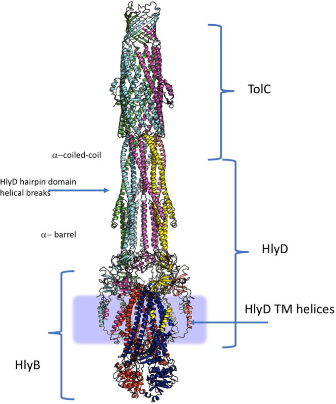
Tripartite efflux pumps and the related type 1 secretion systems (T1SSs) in Gram-negative organisms are diverse in function, energization, and structural organization. They form continuous conduits spanning both the inner and the outer membrane and are composed of three principal components-the energized inner membrane transporters (belonging to ABC, RND, and MFS families), the outer membrane factor channel-like proteins, and linking the two, the periplasmic adaptor proteins (PAPs), also known as the membrane fusion proteins (MFPs). In this review we summarize the recent advances in understanding of structural biology, function, and regulation of these systems, highlighting the previously undescribed role of PAPs in providing a common architectural scaffold across diverse families of transporters. Despite being built from a limited number of basic structural domains, these complexes present a staggering variety of architectures. While key insights have been derived from the RND transporter systems, a closer inspection of the operation and structural organization of different tripartite systems reveals unexpected analogies between them, including those formed around MFS- and ATP-driven transporters, suggesting that they operate around basic common principles. Based on that we are proposing a new integrated model of PAP-mediated communication within the conformational cycling of tripartite systems, which could be expanded to other types of assemblies.


Conflict of interest statement

The authors declare no competing financial interest.

Figures

Figure 1
Figure 1
Representative structures of multidrug transporters and tripartite assemblies. Structures of members of the ATP-driven ATP-binding cassette (ABC) superfamily and the proton-motive force-dependent secondary antiporters of the major facilitator superfamily (MFS), multidrug and toxin extrusion (MATE) family, small multidrug resistance (SMR) family, and resistance nodulation-cell division (RND) superfamily are shown. A substrate for each of the transporters is indicated (colored double triangles). The single-component transporters are independent multidrug/H+ (or Na+) antiporters which transport the drugs from the cytoplasm to the periplasm. The tripartite RND superfamily member MexAB-OprM and the tripartite ABC superfamily member MacAB-TolC are postulated to sequester their substrates from the periplasm (or outer leaflet of the inner membrane) and transport them across the outer membrane. The single component multidrug efflux antiporters and the RND-type tripartite efflux pumps act in a synergistic fashion to efflux drug substrates across both inner and outer membranes. Structures of a proteobacterial antimicrobial compound efflux (PACE) member are elusive and therefore not included in the figure. ABC superfamily members and the 14-transmembrane helix MFS transporters form also tripartite pumps. The ABC superfamily member HlyBD-TolC transports hemolysin from the cytoplasm to the outside of the cell. The ABC-type tripartite MacAB-TolC complex transports macrolide antibiotics, outer membrane glycolipids, lipopeptides, and protoporphyrinand polypeptide virulence factors such as enterotoxin II. The MFS-type tripartite EmrAB-TolC system has been shown to transport several small molecular weight drugs. EmrE Protein Databank (PDB) entry: 3B5D; DinF-BH PDB: 4LZ9; MdfA PDB: 4ZOW; MexAB-OprM EM Data Bank (EMDB) entry: EMD-10395, PDB: 6TA6; EmrAB-TolC adapted from Yousefian et al.; MacAB-TolC EMDB: EMD-3652, PDB: 5NIK; MacB EMDB: EMD-3653, PDB: 5NIL. The HlyB model (based on PCAT1 (PDB: 4RY2)) and the full assembly of the HlyD-docked homology model are provided by V. Bavro. LPS, lipopolysaccharide.
Figure 2
Figure 2
Diverse genetic organization of tripartite efflux systems across a representative sample of Gram-negative bacteria. ABC, ABC-binding cassette; MFS, major facilitator superfamily; RND, resistance-nodulation-division.
Figure 3
Figure 3
Schematic diagram of the different mechanisms of tripartite efflux pump regulation. (A) Local regulation usually involves a TetR family transcriptional regulator, such as AcrR, that acts to locally repress efflux gene expression and maintain basal levels of expression. Global regulation generally involves AraC/XylS family transcriptional regulators, such as MarA, RamA, and SoxS, that activate efflux pump gene expression. These global regulators themselves are locally regulated by their own TetR family transcriptional regulators, such as MarR, RamR, and SoxR. The presence of antibiotics or other external stressors can release these repressors to allow activation of efflux gene expression. Other types of regulators, such as the quorum sensing regulator SdiA, can also activate efflux gene expression. Two component systems (TCSs) consist of a sensor histidine kinase (EvgS) that detects external stimuli, such as drugs, and phosphorylates a response regulator (EvgA), which becomes activated to trigger efflux pump gene expression. Post-transcriptional regulation includes RNA-binding proteins, such as CrsA, that stabilize efflux gene mRNA to promote efficient efflux protein translation. (B) In V. cholerae, the TetR family transcriptional regulator VexR activates expression of the vexAand vexB efflux pump genes.
Figure 4
Figure 4
Overview of the principal components of the tripartite assemblies. The primary and tertiary structures of the main group of proteins involved formation of tripartite efflux complexes and type 1 secretion systems. The coloring of the key structural features is the same on the primary and the 3D structure. (A) Outer membrane factor (OMF) family on the example of the Pseudomonas aeruginosa OprM channel monomer, based on the PDB ID 1WP1. (B) Periplasmic adaptor protein (PAP), also known as the Membrane Fusion Protein (MFP) family, on the example of the Pseudomonas aeruginosa MexA associating with the RND transporter MexB. Two conformers are presented based on the PDB ID 6TA6; see text in section 7.2 for details. (C) A representative RND-family transporter—MexB, from P. aeruginosa. Trimeric assembly based on PDB ID 6T7S. PN and PC—periplasmic or porter domain N-terminal and C-terminal subdomains; DN and DC—docking/funnel domain N- and C-terminal subdomains, respectively. See section 5.1 and Figures 5 and 6 for details. (D) A representative structure of the Major Facilitator Superfamily (MFS) transporter with 14-transmembrane helices based on the POT-family member PepTSo from Shewanella oneidensis. PBD ID 4UVM, monomer presented. See Section Y for details. (E) A dimeric structure of the MacB transporter from E. coli based on PDB ID 5NIK. (F) Representative structure of the ABC transporters involved in the formation of the type 1 Secretion system (T1SS), on the example of Hemolysin alpha exporter HlyB. Dimer structure based on a homology model derived from the peptidase containing ABC transporter PCAT1 structure (PBD ID 4RY2). For details see section 5.6. NBD, nucleotide binding domain; CLD, C39 like domain.
Figure 5
Figure 5
Structure of asymmetric AcrB comprising three protomers in the loose (L, blue), tight (T, yellow), and open (O, red) conformation. (A) Side view of trimeric AcrB along the membrane plane. Indicated are the transmembrane, periplasmic porter, and funnel domains (TMD, PD, and FD). (B) Top view on the porter domain. In the L protomer (blue), the PN1, PN2, PC1, and PC2 subdomains are indicated. The PC1 and PC2 subdomains constitute a cleft as part of the access pocket (AP, dashed oval). The T protomer contains also an open PC1/PC2 cleft but is less voluminous compared to the one in the L protomer. Between the PN2 and PC1 subdomains, the deep binding pocket (DBP, dashed oval) is indicated. The switch loop (green) separates the AP and the DBP. In the O protomer (red), the PC1/PC2 cleft, the AP, and the DBP are closed. From the closed DBP, a tunnel is present which exits at the funnel domain. In the asymmetric LTO AcrB porter domain representations (top view) on the left, binding of drugs to the access pocket is shown. Rifampicin (sphere representation in pink) binds in the L protomer (highlighted in blue) at the proximal side of the access pocket, and erythromycin (sphere representation in pink) binds to most distal part of the access pocket, underneath the switch loop (green). On the right, the T protomer is highlighted (in yellow), and bound minocycline (sphere representation in pink) is located in the distal groove region of the deep binding pocket,, whereas puromycin (sphere representation in cyan) binds to the more proximal cave region of the deep binding pocket underneath the switch loop (in green). (C) Top view of the funnel domain (FD). The N-terminal FN and the C-terminal FC subdomains are indicated. The AcrB trimer is stabilized by a loop protruding from the FN subdomain connected to the FD subdomain of the neighboring protomer emerging from subdomain DN to DC of the adjacent protomer. The distal FD remains largely unaffected by the conformational cycling and remains structurally unchanged during the LTO cycle. (D) Top view (from the periplasm) of the transmembrane domain (TMD). The TMD displays 12 transmembrane helices (TMHs). The proton relay network consists of residues D407, D408, and K940 associated with R971 and T978 located in the center of the TM-domains. Adjacent protomers interact via TM1 and TM8. The large central cavity is depicted by a circle. This image was constructed with PDB 4DX5 (in complex with minocycline) for the structure images in complex with drugs. Coordinates for rifampicin (PDB 3AOB), erythromycin (PDB 3AOC), minocycline (PDB 4DX5), and puromycin (PDB 5NC5) were superposed to the 4DX5 structure.
Figure 6
Figure 6
Topology of AcrB protomer. The structure of AcrB is a representation of an architecture that is shared across the HAE and HME families of RND transporters. The protomer of AcrB presents a pseudo-2-fold symmetry, associated with a gene duplication of the ancestral gene, giving two semi-identical N-terminal and C-terminal portions of the protein, each including a 6 TM-helical component with a large periplasmic loop spliced between the TM1/TM2. These loops form the porter or periplasmic domain (PD) and a docking domain. Porter domains display highly modular organization, presenting a mixed α-β sandwich of a general (β–α–β–β–α–β) configuration dubbed the PD-module (lower inset). This is repeated through the porter subdomains PN1/PN2 (belonging to the N-terminal loop) and PC1/PC2 (C-terminal loop), respectively. Subdomains PN1/PC2 and PN2/PC1 form discrete units coupled by a shared β-sheet. The docking or funnel domain comprises two subdomains, DN (or FN) and DC (or FC) respectively, which are topologically derived from the basic PD-fold of the PN/PC domains, by a flippage of the β2-β3 hairpin out of the central β-sheet (upper inset). The long β-hairpins of the DN and DC domains connect neighboring protomers by forming interprotomer β-sheets.
Figure 7
Figure 7
Structural features of AcrB. The asymmetric AcrB trimer comprises three protomers adopting different conformations (L, loose—blue; T, tight—yellow; O, open—red). (a) AcrB can be structurally subdivided into a funnel (FD), a porter (PD), and a transmembrane domain (TMD). The TMD consists of 12 transmembrane helices (TMs) per protomer (shown are the L (blue) and T (yellow) protomers; the O protomer is omitted for clarity). The TMD of the three protomers encloses a central lipid-filled cavity. Likewise, the FD of the AcrB trimer forms a funnel region, which is exposed to the channel structures of AcrA and TolC and facilitates the export of drugs across the OM. (b) Drug entrance sites are highlighted on the L protomer (blue). The vestibules are interprotomeric entrance channels (shown here is the vestibule between the O (red) and L protomers) toward the central cavity. The indicated TM7/8 groove in the L protomer is the entrance toward channel 1 (CH1, shown in panel c). This groove is also present in the T protomer. The cleft between the PC1 and PC2 subdomains, apparent in both the L and T protomers (indicated only for the L protomer), is the entry side for channel 2 (CH2, shown in panel c). (c) The asymmetric AcrB trimer comprises substrate entry channels in the L and T conformations. The entrance of channel 1 (CH1) starts above the TM8/TM9 groove and guides substrates from the outer leaflet of the inner membrane to the AP and further to the DBP. The cleft pathway via channel 2 (CH2) likewise leads to the AP. Compounds sequestered in the central cavity via the vestibules between the protomer interfaces can access channel 3 (CH3) for transport directly to the DBP. All entry channels are closing during the T to O transition. Concomitantly, an exit channel is created in the O protomer that connects the closed DBP to the FD.
Figure 8
Figure 8
Drug binding to the DBP of the AcrB T conformer. Superimposition of the coordinates of minocycline (MIN, carbon = green; PDB: 4DX5), doxorubicin (DOX, carbon = violet; PDB: 4DX7), rhodamine 6G (R6G, carbon = pink; PDB: 5ENS), and puromycin (PUY, carbon = orange; PDB: 5NC5) in the DBP. Substrates are shown as sticks, the PN2/PC1 subdomains are represented as a cartoon, colored in yellow. The switch-loop is highlighted in green.
Figure 9
Figure 9
Proton binding or release induces conformational change of the transmembrane domain structural repeats. (A) Substrate/proton antiport catalyzed by AcrB can be described by two coupled mechanisms. A conformational switch from L (blue) to T (yellow) is mediated by substrate binding in the DBP of the porter domain. The rearrangement of subdomain unit PN2/PC1 leads to a downward movement of linked TM2. Consequently, the TMR1–TMR2 interface rearranges and opens a periplasmic proton entry site. Protonation of residues D407 and/or D408 results in separation of the TMR1–TMR2 interaction network. A conformational change to the disengaged state results in a switch to the O-conformation (red). TM2 moves upward and the upper part of TM8 undergoes a random-coil-to-helix transition, while binding pockets in the porter domain collapse and the exit channel becomes accessible. The proton binding site opens to the cytoplasmic side. Protons are released in the cytoplasm, down the electrochemical gradient. Charged D407 and/or D408 switch the TM domain back to the engaged state. This conformational change translates back to the porter domain. Proton entry and exit are presumably mediated through a network of water molecules. (B) Close view of the proton relay comprising D407, D408, K940, and R971. These residues undergo the most dramatic conformational change during the T to O transition. In the L (blue) and T (yellow) conformations, water molecules mediate electrostatic contact between D407/D408/K940 with R971. In the O state (red), the transmembrane domain is (almost) dehydrated, greatly affecting the pKa values of the titratable residues. (C) Insight into the structural details of the interaction of D407 in the O conformation; the H-bonding interaction of the carboxyl group of D407 with the carbonyl group of G403 is only possible if D407 is protonated. A central water molecule connects (by hydrogen bonding) the interaction partners on TM4 (D407), TM10 (K940), and TM11 (T978).
Figure 10
Figure 10
General topology of MFS transporters based on a representative of the structure of E. coli EmrD (PDB ID: 2GFP). The topological diagram highlights the inverted structural repeats, forming the N- and C-terminal lobes of the transporter, suggesting multiple gene duplication events.
Figure 11
Figure 11
Alternating access mechanism by MFS transporters. The transport cycle of MFS proteins seems to involve ordered binding and release of proton and substrate; however, drug/proton stoichiometry varies between family members.
Figure 12
Figure 12
General view of the type IV ABC transporter topology and features of the typical type IV ABC transporter structure. Schematic representation of the topology of the isolated monomer of ABC transporters belonging to the type IV group (panel A) and the dimeric formation (panel B), highlighting the cross-protomer engagement of the nucleotide binding domains (NBDs) by the coupling helices 1 and 2 (CH1 and CH2, respectively). The optional N-terminal C39 or C39-like domain (CLD), which is present in a subset of the family, is shown as a “packman”. The TMD is presented as a rainbow from N- to C-terminal, and the EH represents the elbow helix. The second protomer of HlyB is presented in gray. Approximate membrane boundaries are represented by the blue rectangle. (C) View of a microcin-transport associated McjD based on the PDB ID 4PL0 (two side views 90° apart) highlighting the principal structural elements. Coloring as in panels A and B. (D) PCAT1 in complex with its transported peptide CtA, based on the PDB ID 6 V9Z. The C39-domain is colored wheat.
Figure 13
Figure 13
C39 and CLD domains in AMS/PCAT transporters. (A) Structure of the catalytically active C39 domain from PCAT1 (based on PDB ID 6V9Z). The main elements of the secondary structure, as well as the key catalytic residues are highlighted. (B) The structure of the C39-like domain (CLD) of the HlyB transporter in identical orientation based on PBD ID 3ZUA. While the general architecture is preserved, the active site cysteine residue is substituted by a tyrosine.
Figure 14
Figure 14
PCAT–cargo interactions mediated by their C39 and CLD domains. (A) Side view of the PCAT1-CtA transporter–cargo complex based on the PDB ID 6 V9Z (Kieuvongngam et al.). (B) Zoomed-in view of the C39 domain highlighting the interaction with the secretion signal of the CtA. (C) Structure of the equivalent CLD domain in HlyB, with CtA superposed into the substrate binding groove. (D) View of the CtA-threading into the substrate binding cavity of PCAT reveals the large substrate access cavern delineated by TM4 and TM6. (E) Position of the cargo targeting motif of the CtA on the surface of the C39 domain, indicating the location of the conserved hydrophobic residues which provide the docking and the GG-motif where the proteolytic cleavage occurs.
Figure 15
Figure 15
Structure of the ABC transporter nucleotide-binding domains (NBDs). (A) Linear graph from the N- to C-terminus of the typical NBD domain, using HlyB as a template. (B) View of the dimerized NBD based on the crystal structure of the ATP-bound HlyB monomer (PDB ID 1XEF), highlighting the positions of the conserved sequence motifs involved in nucleotide binding. In one subunit, the RecA-like and β-sheet domain is colored pale blue, while the α-helical subdomain, harboring the ABC-motif, is colored yellow. The second NBD protomer is colored wheat. Motifs are presented in colors matching the sequence boxes in panel A. For illustrative purposes, the side chain of the catalytic H662, which is substituted by an alanine in the above structure to stabilize the ATP-bound state, is being modeled in. The side chains of Y477 (loop A; coordinates the adenine ring of ATP); the E631 (the invariant Glu-residue following Walker B, which helps to coordinate the ATP) and H662 (H-loop) are presented as sticks. The Walker B motif usually features four hydrophobic residues that form a β-strand and is terminated by a conserved Asp (in this case D630), which coordinates the catalytic Mg2+ cofactor via water-molecule mediation. Two ATP molecules are colored in purple.
Figure 16
Figure 16
Modified alternating-access mechanism of PCAT1. CtA is recruited and cleaved in the inward-facing (IF) conformation. In the model by Kieuvongngam et al., the substrate specificity of the transporter is conferred primarily, if not exclusively, by the interaction of the C39-domains with the leader peptide, and the transporter TMD essentially does not otherwise interact with the cargo. In a modification of the cycle proposed by Rachman and Mchaourab, the cargo is at the center of the interaction, as cargo interactions have been observed in transporter variants lacking C39-domains. In both cases, the interaction of the cargo proteins with the TMD leads to subsequent cleavage of the leader peptide, and a transient inward closed conformation (IC), similar to that observed in the McjD, is created, which enables the ATP binding. ATP-binding drives conformational changes in the TMD leading to occlusion of the cargo protein binding chamber, known as the outward occluded state (not shown). ATP binding stabilizes the outward-facing (OF) conformation in which the PEP domains are disengaged. After cargo release, TMDs isomerize to form an occluded state (OCC) in the absence of cargo. The energy of ATP-hydrolysis resets PCAT1 back to the inward-facing conformation, allowing PEP to dock into the TMD–NBD interface. Padlock indicates the closure of the outer “gate” of the transporter.
Figure 17
Figure 17
General organization of PCAT transporters associated with T1SS. (A) AaPrtD based on the PDB ID 5L22. Note the highly kinked TM3 and TM6 and the supposed “substrate entry window”. Unlike the PCAT transporters discussed previously, the AaPrtD does not present a wide substrate binding cavity and is suggested to transport unfolded cargoes. The ADP moiety (in red spacefill) is found bound to the protomers. Note the lack of CH1 helix at the end of TM2. (B) Homology model of HlyB, highlighting features common to both PCAT1 and PrtD. The CLD-domains are predicted to aid positioning of the cargo into the substrate entry window.
Figure 18
Figure 18
The function of the tripartite pump MacAB-TolC in toxin secretion and macrolide resistance. MacAB secretes ribosomally synthesized and post-translationally modified peptides (RiPPs), such as enterotoxin STII, that are targeted and exported to the periplasm by the SecY-secretion signal (purple). Following cleavage and disulfide bond formation in the periplasm, the toxin is then secreted out by the MacAB-TolC. Figure modified based on Crow et al.
Figure 19
Figure 19
Structural organization of MacB. (A) General topology of the single MacB protomer highlighting the N-terminal nucleotide binding domain (NBD; magenta), the connecting helix (CoH), the transmembrane domain (TM domain) with its four helices, as well as the periplasmic core domain (PCD), which is composed of a PD-module and a SABRE subdomain (green). CH1 and CH2, coupling helices 1 and 2, respectively. (B) Two orthogonal orientations of the single protomer of MacB from A. baumanii based on PDB ID 5WS4, highlighting the principal secondary structure elements. The blue oval delineates the PD. (C) View of the complete MacB-dimer.
Figure 20
Figure 20
Comparison of the porter domain of RND transporters and PCD of MacB. (A) The lower part of the periplasmic domain (PCD) of MacB shares structural homology with the porter domains (PD) of the RND transporters, as can be seen on the example of the AaMacB (PDB ID 3FTJ) (right) and the PC1 PD module of AcrB (PDB ID 2DHH) (left). (B) The topology diagram of the domain indicates that the SABRE subdomain is spliced within the core PD module between the β2 and β3 strands.
Figure 21
Figure 21
Diversity of PCD domains in the FtsX/MacB family and porter domain connections. (A) The basic PD-module of the PCD is conserved across the MacB/FtsX family; however, there are multiple variations on the theme. The architecture of the module is expandable, but intriguingly, it features conserved regions of insertion, which are shared not only between Gram-positive and Gram-negative bacteria but also with eukaryotic organisms. The PDB codes for presented structures are as follows: Mycobacterial FtsX (4N8N); SpFtsX (6HE6); Spr0695 (5XU1); LolC (5NNA); NPC1 (5U74); DISP (6XE6). (B) PD domains present in different proteins outside of the MacB-family (see text for more details).
Figure 22
Figure 22
Topological connections of the basal RND PD-module and the docking/funnel subdomain in RND transporters. (A) The upper panel presents the topological diagrams, demonstrating the DN domain could be derived from the basal PD-module by flipping out the β2/β3 hairpin which forms part of the central β-sheet. This disrupted cental sheet is complemented by the corresponding β2/β3 hairpin of the neighboring subunit by β-augmentation. Note that the antiparallel character of the central sheet changes as a result. PD1 AcrB denotes the organization seen in PN1/PC1 subdomains. (B) The crystal structures of the corresponding modules on the example of the AcrB PC1 subdomain (PDB ID 2GIF) and the DN1 subdomain of CusA (PDB ID 2DHH).
Figure 23
Figure 23
Different families of RND transporters and related proteins. The representatives of the SecDF family, as well as the prokaryotic MmpL and Hopanoid transporter groups are shown, as well as the known structures of eukaryotic RND transporters. The PDB ID codes are given in parentheses. Due to the poor resolution and disorder, the missing loops of the DISP1 have been modeled for completeness. See text for more details.
Figure 24
Figure 24
Structural transitions within the PD-domains of SecDF are linked to the functional cycle of the transporter. The PD modules in the periplasmic domains of SecDF (P4 and P1-base) undergo a conformational transition from β-barrel to β-sheet between the Super F form (as seen in the PDB ID YHF) and the F-form (PDB ID 3AQP). Modified based on Furukawa et al. These are linked to the substrate engagement by the P1-head domain of the transporter, and similar transitions may occur within other PD-containing transporters, e.g., the PD-domains of the MacB/FtsX family.
Figure 25
Figure 25
PD domains provide a flexible modular architecture which is shared across a number of different transporters. (A) Topological diagram showing the decoration of PD domains in different transporter classes. Where the transporters are not homooligomers with a single PD module per domain, the PD1 and PD2 domains of respective subunits are presented. The insertion points are limited and conserved across the known PD-domains, with notable splicing events taking place between β2 and β3 of the central β-sheet. Minor β-hairpin decorations are seen in the FtsX family and eukaryotic RND transporters. In addition, the SecDF family displays a unique insertion between α2 and β4. (B) Gallery of the PD-domains of the notable members of the transporter families discussed above. The domain abbreviation and PDB ID code of the respective structures are provided in parentheses. Abbreviations: MLD, middle luminal domain; ECD1/2, extracellular domain 1/2; CTD, C-terminal luminal domain or Cys-rich domain.
Figure 26
Figure 26
(A) Schematic representation of the TM helix packing at the dimer interface between different classes of ABC transporters shows close connections of the MacB architecture to the type VI and type VIII (MlaEF) transporters. Topologies are derived from the structures of MacB (PDB ID 5GKO), MlaE (PDB ID 6XBD), LptB2FGC complex (PDB ID 6S8N), Wzm-WznT (PDB ID 6M96), and ABCG2 (PDB ID 5NJG). Top-down view from the periplasm. Note: due to the intertwisting of the helices in the type IV transporters, the diagram depends on the level at which the slice is cut through the TM; the provided view is representative to the middle of TM segment, based on the ABCB1 structure (PDB ID 6QEX). (B) Topological connections within the ABC transporter families. The ABC transporter families share a common core architecture, which can be derived from the four TM helices seen in the type VII (MacB/FtsX) family. The other main families of exporters are presented, which could be seen as derived from MacB by addition of C-terminal helical fragments. Homologous helices are colored consistently from the N-terminal to the C-terminal. The intracellular coupling helices (CH1 and CH2) are presented in green and red. CoH = connecting helix. Substrate binding domains are shown as gray boxes (PCD, periplasmic core domain; PH, pore helix; PGH, periplasmic gate helix; ECD1,2, extracellular domains 1, 2; β-JR, β jelly roll domains). Adopted with modifications based on Schaeffer et al.
Figure 27
Figure 27
Mechanotransmission mechanism of MacB. Crystal structures suggest a possible cycling mechanism for MacB. In the nucleotide-free structures, the NDBs of the transporter are separated and appear unable to bind ATP. This coincides with the separation of the PCDs and lack of helical-bundle formation in the stalk helices. To the contrary, the ATP-bound forms show significant rearrangement of the PCDs, which also coincides with a helical bundle formation in the TM-domain, suggesting that the ATP-binding is communicated long-range from the NBDs across the membrane to the periplasmic domain through the TM-stalk helices. This has been dubbed “mechanotransmission”, as the stroke from ATP-binding is not used to transport the substrate across the membrane in which the ABC transporter resides but rather to cause conformational changes in the periplasm. (Modified, based on the model by Crow et al.)
Figure 28
Figure 28
General organization of the typical OMF channel on the example of OprM. (A) Topological diagram. Principal helices (H) and β-sheets (β) are denoted. The chain is colored rainbow from the N-terminus to the C-terminus. Pseudosymmetry within the protomer provided by the structural repeats, arising from a gene duplication event, is evident. (B) 3D structure based on the palmitoylated OprM structure (PDB ID 4Y1K). See text for more details.
Figure 29
Figure 29
(A) Highlight of the conserved amino acids among 5 OMFs. The protomeric structures of TolC (1EK9, blue), OprM (3D5K, purple), VceC (1YC9, ochre), CmeC (4MT4, green), and CusC (3PIK, red) are shown in the upper part of the panel. The side chains of the preserved residues are represented as spheres of different colors according to their intrinsic location in the protein: orange for the β-barrel part, green for the equatorial part, and blue for the periplasmic part. The position of each conserved amino acid within the primary sequence is shown in the table in the lower part of the panel. (B) Visualization of the β-barrel domains within the quaternary structures of 5 OMFs. Each porin retains the same structural color as in panel A. Two views are shown: a side view first and a top view second.
Figure 30
Figure 30
“Knobs into holes” packing analysis of the helix–helix interfaces of TolC. (A) The structure of TolC (PDB ID: 1EK9) is visualized as a ribbon, with residues forming canonical coiled-coils (yellow and orange spheres) and residues forming noncanonical coiled coils (red and blue spheres). (B and C) A closer look into the knobs-into-holes packing patterns at the interfaces between α-helices, which are also depicted in “ladder” representation. Helical IDs are listed at the top, and amino acid residues are specified by the one-letter code. Heavy lines and bold helix identification numbers correspond to α-helices viewed from the exterior, while dotted lines and light identification correspond to α-helices viewed from the interior. (B) The layout of the four interfaces between α-helices participating in the construction of the 12-helix tube forming the α-cylinder. (C) The layout of the two interfaces between α-helices in the construction of the four-helix bundle forming the canonical coiled-coil restricting the periplasmic extremity of the TolC channel.
Figure 31
Figure 31
View of the periplasmic tip of representative OMFs: TolC (1EK9), OprM (3D5K), CusC (3PIK), and BesC. (A) TolC. (B) OprM. (C) CusC. (D) BesC. Structures are shown as cartoons, and residues involved in the channel gating are shown as ball and sticks representation, colored depending on the type of interactions between them. In the resting state of the channels, the trajectories of the H7/H8 helices are bent and they are prevented from adopting a relaxed superhelical trajectory by anchoring interactions with the H3/H4 helices, known as “primary gates”. These are suggested to be disrupted upon interaction with the helical-hairpins of their PAP-binding partners. Intraprotomer interactions within primary gates are colored red; interprotomer interactions are shown in orange; van der Waals interactions forming the hydrophobic gates in, e.g., OprM and CusC are colored blue. The aspartate ring forming the “secondary” gate is shown in gray. The predicted primary gates of BesC (homology model), from the B. burgdorferi pump BesABC, which operates with the PAP BesA, that lacks the helical hairpin domain, are significantly less stable.
Figure 32
Figure 32
Periplasmic view of TolC in its resting, closed conformation (PDB ID 1EK9) and after full dilation of its aperture upon engagement with the PAP protein as seen in the assembled tripartite complex PDB ID 5NG5. Structures are shown as cartoon view, and aspartate D374 is shown as ball and sticks. Distances between hydroxyl groups of the carboxylic acid of D374 are measured.
Figure 33
Figure 33
Diversity of PAPs suggesting promiscuity of assembly. (A) In Salmonella, at least eight different tripartite assemblies are formed with the participation of the OMF TolC. (B) In Anabaena sp. PCC 7120, the OMF HgdD partners with at least eight different PAP–transporter pairs. Notably, while the tripartite assemblies in Anabaena are dominated by MacB and ABC transporters, the RND-based assemblies are predominantly represented in Salmonella. The established roles of the ABC transporters in the lower panel are indicated.
Figure 34
Figure 34
Structural organization of a typical PAP based on the structure of the MexA from Pseudomonas aeruginosa (PDB ID 6TA5). The topological organization of the principal PAP domains is shown on the right. The polypeptide chain of the PAP has a form with a hairpin-like fold with both N- and C-termini being close to the membrane and both the N- and C-terminal parts of the protein contributing to each domain. The N-terminal cys-residue that is lipidated in the RND-associated PAPs is highlighted in yellow.
Figure 35
Figure 35
Hexamerization of PAPs and the formation of the helical–hairpin nanotube. RLS-motif of PAPs and its conservation across different groups. (A) General view of the MacA hexamer from PDB ID 5NIK, highlighting principal domains. (B) Close view of the hairpin domains presenting the RLS signature motif. (C) Top-down view of the lipoyl-ring of MacA as seen in PDB ID 3FPP. The N209 from the “gating ring” is restricting the channel in the hexameric form. (D) Canonic RLS-motif as seen in RND- and MacB-associating PAPs. (E) Overlay of the tips of the hairpin domains of MacA and AcrA showing close conservation of the RLS-motif. (F) Overlay of the tips of the hairpin domains of MacA and T1SS-associated HlyD shows deviation from the canonic sequence.
Figure 36
Figure 36
Different types of PAPs associated with different efflux systems. Comparative structural gallery of PAPs of known 3D structure, colored by domain. Membrane proximal domain (MPD) in red; β-barrel domain in green; lipoyl in blue; α-helical-hairpin in gold. From left to right: BesA (PDB ID 4KKS); HME-associated CusB (PDB ID 3OW7); HAE-1 associated MexA (PDB ID 6TA6); MacB-associated MacA (PDB ID 5NIK); MFS-associated AaEmrA (PDB ID 4TKO); and T1SS-associated HlyD (PDB ID 5C21). The missing loops and transmembrane fragments of MacA/EmrA and HlyD have been modeled for illustrative purposes. Note that only RND- and MacB-associated PAPs appear to contain MPDs, while the spirochaetal BesA lacks the α-helical–hairpin domain altogether.
Figure 37
Figure 37
Modularity of the assembly of tripartite complexes. A schematic representation of the different tripartite assemblies based on their transporter types reveals striking correlation with the domain composition of the PAP proteins associated with them. PAPs of the MFS- and T1SS ABC transporter-based complexes lack MP domains, which is also correlated to the transport of their cargoes across the inner membrane (IM). On the other hand, the MacB and RND transporter-based assemblies pick their cargoes from the periplasmic side of the membrane associated with PAPs that have MPDs, hinting toward their role in presentation of the cargo to the transporters. Notably, the β-barrel domains of the PAPs are universally present and allow adaptation to diverse transporter stoichiometries.
Figure 38
Figure 38
Structural organization of the PAP β-barrel domains links them with β-barrel domains in flagellar basal body proteins. (A) Structure of the isolated β-barrel domain of the MFS-associated PAP EmrA, based on PDB ID 4TKO. (B) Topological diagram. The lipoyl and α-hairpin domains can be seen as inserted between the β1- and β2-strands of the β-barrel. (C) Structure of the C-terminal domain of the flagellar basal body protein FlgT from Vibrio.
Figure 39
Figure 39
(A) Structural connections of the β-barrel domains in the rotary ATPases and the T3SS-associated ATPases. (B) The β-barrel domains of PAPs structurally homologous to those found in the rotary ATPases. Secondary structure elements are color coded identically to the topological diagram in Figure 38. (C) Overlay of the C-alpha backbone between EmrA and F1-ATPase β-subunit highlights their close structural homology.
Figure 40
Figure 40
Connection between β-barrel domains and rotary ATPases. (A) Upper panel. A view of the hexameric assemblies presented by the rotary ATPases and PAP β-barrel domains. (B) Left, side view of a hetero-oliomeric F1F0-ATPase from E. coli; Center, type 3 secretion system associated ATPase EscN from E. coli. Right, CusBA subcomplex from E. coli. The hexameric β-barrel rings are highlighted by the red parallelogram, with individual subunits being red and magenta.
Figure 41
Figure 41
Helix–turn–helix motifs in PAPs and OMF that are supposed to mediate their interaction. (A) Schematic view of the coiled coil packing within the α-helical hairpin of the PAP showing its antiparallel interface. Conserved hydrophobic residues are interacting within the a and d positions of the respective N- and C-helices (projection view looking down the hairpin helices outward from the lipoyl domain). (B) A view of the α-helical hairpin tip of AcrA (based on PDB ID 2F1M), highlighting the interaction positions a and d; V126 (a) and A146 (d); and Y129 (a) and Y143 (a) form heptad-pairs. (C) The RLS-motif is present at the tip of the HTH motif of the PAP hairpin. Presentation of the classic-RLS-motif as observed in the (predominantly) RND- and MacB-associated assemblies, while MFS-associated PAPs show a deviation in the second half of the motif, and the T1SS-associated PAPs only retain a positively charged residue in the front of the motif, suggesting a different association with the OMF. Consistent with the lack of cognate OMFs, the PAPs in the Gram-positive organisms do not share any recognizable RLS. (D) R1 and R2 HTH-motifs at the tip of the static (H3/H4) and mobile (H7/H8) helices of the OMFs present a loosely conserved VG(L) motif, which is suggested to interact with the connecting loop of the RLS in the PAPs. Alignments in this figure have been visualized with Espript3.
Figure 42
Figure 42
Interaction between the tip-regions of OMFs and PAPs on the example of OprM and MexA. (A) Side view of the MexAB–OprM complex as seen in the cryo-EM structure (PDB ID 6TA6(270)). The zone of PAP-OMF interpenetration is indicated by the rectangle. Helices of the respective OMF protomers are shown in red, green, and blue; while the α-helical hairpins of PAP1 and PAP2 are colored orange and magenta, respectively. (B and C) Zoom on the tip-to-tip interaction between OprM H3/H4 and H7/H8 helical tips (shown in blue and green, respectively) and the docked α-hairpins of MexA (shown in orange (PAP1) and magenta (PAP2)). Principal interacting residues are shown (proposed RLS-motifs are in bold). (D and E) Schematic view of the MexA channel and associated PAP protomers looking up the channel in closed and open (MexA-MexB-engaged) form, respectively. The binding of PAP1 protomer to the interprotomer interface is suggested to result in destabilization (orange dotted arrow in D) of the interprotomer gates (indicated by the cyan arrows), resulting in an outward swing of the mobile helices H7/H8 (black curved arrows), which are still attached to the H4 via intraprotomer interactions (gray arrow). The initial relaxation of the H7/H8 allows the docking of PAP2, which in turn destabilizes the intraprotomer gates (see the pink dotted arrow in E), leading to full dilation of the OMF aperture. While the exact gating residues differ between the specific PAP–OMF pairs, the general mechanism of PAP docking and relaxation of H3/H4 helices is suggested to be conserved. See the text for more details.
Figure 43
Figure 43
Two nonequivalent binding sites on the surface of the RND transporter accommodate two distinct conformers of the PAP, which serve distinct functions during the cycling of the pump. (A) Side view of the MexAB-OprM assembly (PDB ID 6TA6) showing the binding of the intraprotomer-PAP subunit (PAP1) (orange) and the interprotomer-PAP subunit (PAP2) (magenta). The different RND subdomains are colored, and neighboring RND protomer is colored gray. (B) Cartoon representation of the same angle of view labeling the different subdomains of the PAPs and RND. (C) Isolated views of the contact areas of the PAP1 and PAP2 relative to the RND; for clarity the lipoyl and hairpin domains which do not contact the transporter have been removed.
Figure 44
Figure 44
Comparison of interprotomer interfaces of RND transporters in isolation and upon PAP binding. (A) Side view of the superposition of the T-protomers of AcrB (as seen in asymmetric LTO and symmetrized TTT structures) and MexB (LTO) as seen in tripartite complex as observed in PBD ID 6TA6. RND-conformers are colored: L, blue; T, yellow; O, red; PAP2 confomer, green. (B) Top-down view of the trimeric assemblies of MexB solo (PDB ID 6T7S), MexB “trio” from the tripartite MexAB-OprM structure (PBD ID 6TA6), and the AcrB (TTT-form stabilized by the presence of the MBX3132 inhibitor) (PBD ID 5NG5).
Figure 45
Figure 45
Conformational cycling of AcrB/MexB protomer and trimer in dependence of PAP engagement and disengagement. The tree panels present different aspects of the interaction focusing on the PAP-OMF (top) and PAP-RND (middle and bottom). In the upper panel the engagement state of the periplasmic adaptor protein conformer 2 (PAP2) is indicated based on the studies by Tsutsumi et al. and Glavier et al. Moreover, as an extension of the previous models,,,, the closed state structure (denoted “C”) found by Glavier et al. is implemented, as well as the structural interpretation by Glavier et al. concerning the engaging role of PAP2 at the AcrB/MexB interprotomer interface. In the middle panel, the conformational cycling of a single RND protomer is shown (l-protomer, blue; T, yellow; C, gray; O, red). Whereas all PAPs (PAP1, PAP2) form a stable hexameric arrangement via their β-barrel and lipoyl domains, the membrane proximal domains (MPDs) are anticipated to be in a disengaged or engaged state. The binding of the MPD-domain of the PAP2 is suggested to take place at the interprotomer interface of the RND. The interprotomer crevice is closed between L and L (LL) as well as in LT and OL. Between TT this interface crevice is widened, and in TO, the gap is large. In the lower panel the conformational state of the protomer shown in the upper panel is given in relation to the states of the other protomers in the trimer (“wheel” representation). The role of the PAP2 MPD engagement is postulated to be supportive for the direction of the cycling (L → T → O → L), preventing the backward sliding of the O-to-T state by acting as a molecular latch. The complete conversion from L to O in the presence of substrate (S) including the protonation of the TMD and the release of the substrate from the O protomer is suggested to be PMF-independent and might explain why the LTO conformations are observed in isolated protein samples upon structural analysis. The return from the O state to the L state, however, is a PMF-dependent step in analogy with the ABC transporter cycle shown in Figure 16. FD, funnel domain; PN1, PN2, PC1, and PC2 are the subdomains of the AcrB/MexB porter domain; TM2 and TM8 are the transducing helices coupling energy transduction from the porter domain to the TMD and vice versa); TMD, transmembrane domain.
Figure 46
Figure 46
Proposed model for concerted tripartite assembly along sectional views of the OMF-PAP-RND interaction surface. RND protomers are colored according to their adopted conformation (Loose in blue, Tight in yellow, Closed in gray and Open in red). Six PAPs protomers bind as pairs to the RND trimer. The resting, closed OMF trimer interacts with the PAP hexamer (one pair of PAPs is omitted for clarity). Upon interaction with the OMF periplasmic end, PAP1 destabilizes the lock anchoring the H7–H8 helices to the static H3–H4 helices, resulting in a spontaneous relaxation of the superhelical trajectories of H7–H8 helixes as depicted by arrows. Engagement with the OMF is communicated down to the RND via PAP2, allowing the positioning of the MP-domain at the T/C crevice (indicated by the pink arrow), which in turn results in a rearrangement in the underlying PN1 domain leading to the opening the helix gate, denoted by the rotation of the flap symbol, thereby enabling the Closed to Open transition of the protomer.
Figure 47
Figure 47
Qualitative energy diagram of the assembly and cycling of the RND-tripartite assemblies taking into account the role of the PAPs and the newly discovered C-to-O transitions. The symmetrical LLL state is suggested to be a metastable high-energy state of the RND trimer and is prone to spontaneous collapse upon substrate binding. The L to C transitions are suggested to be driven solely by the binding energy between the components and can occur in isolated RND transporters, as witnessed, e.g., by the “mono” structures of MexB. The C-to-O transition does not happen spontaneously, suggesting that the C-to-O is an upper energy transition and is offset by the binding of the PAP2 MPD (represented by the lower part of the magenta protomer being colored in orange). PAP2 MPD cycling provides directionality of the cycle and prevents backsliding of the C/O-to-T which in its absence is suggested to be in an unstable equilibrium. The energy from proton release allows for the upper-energy level O-to-L conformational transition, which enables repeat of the cycle.
Figure 48
Figure 48
Comparison of the binary CusBA complex and MexAB-trio suggests a possible pathway of conformational reorganization of the PAPs upon engagement with the OMF. (A) Crystal structure of the CusBA subcomplex as seen in the PDB ID next to the cryo-EM MexAB-OprM structure (PDB ID 6TA6), showing significantly different orienations of the helical hairpins and the difference in packing lipoyl domains of their PAPs. Also, while PAP1 conformer binds at the approximately equivalent interface of the RND surface, the PAP2 conformer, and particularly its MPD domain, appears divergent. (B) Several snapshots from a molecular morphing movie illustrating a possible transition from the OMF-free state to the OMF-engaged state, suggesting possible reorganization of alignment of the helical bundle between the two PAP forms (shown in yellow arrows), as well as the proposed dislocation of the PAP2 MPD within HAE1-systems, which may reflect the engagement of PAP2 in the apo- and OMF-engaged state of the complex.
Figure 49
Figure 49
AcrBZ co-structure. The asymmetric AcrB trimer (gray cartoon) with the three protomers in the L (loose), T (tight), and O (open) conformations. The auxiliary transmembrane modulator AcrZ (raspberry cartoon) is located at the surface periphery on each of the AcrB protomers at the transmembrane domain. The X-ray structure display (PDB: 5NC5) was solved in complex with DARPins (not shown) and puromycin (PUY, orange spheres).
Figure 50
Figure 50
MacAB-association highlighting the differential binding of PAP protomers based on PDB ID 5NIK. Different PAP protomers can be named PAP1-PAP3 based on their interaction with the MacB transporter in an analogy to the RND transporter complexes. PAP1 can be seen as an intraprotomer relative to the transporter, while PAP2 interacts exclusively with the SABRE subdomain of the same transporter protomer. PAP3 appears to occupy an interprotomer position extending over the cleft between the neighboring transporter protomers. (A) Top view looking down at the interprotomer interface of MacB. (B) Side view showing the position of the β-barrel gasket of the PAP hexamer. (C) Different PAP conformers make inequivalent contacts with the crown of the transporter, and PAP3 in particular, which is interprotomer-bound, is loosely associated with the complex.
Figure 51
Figure 51
Comparison of the assembly of MacAB with the MlaEF-complex reveals a common organization. Both transporter complexes are stabilized by a hexameric β-barrel gasket (colored green and red), formed of their respective periplasmic partner proteins, which, although structurally nonhomologous, provide an identical solution to binding to a dimeric transpoter interface. Left, a homology model of the MacAB subcomplex based on the PDB ID 5NIK, taking into account the transmembrane portions of the MacA which were unresolved in the cryo-EM structure, indicates that these are of sufficient length to reach the connecting helix (CoH) of MacB and could provide additional allosteric coupling across the membrane, as established for the MlaEF-D complex (on the right, experimental structure (PDB 6XBD)).
Figure 52
Figure 52
Modified molecular bellows mechanism for the MacAB-TolC pump. MacA (green-cyan) and MacB (blue) undergo allosteric conformational transitions (symbolized by orange arrows) upon binding of substrate and ATP. Similar to type IV ABC transporters, substrate binding is suggested to bring a conformational transition that enables the nucleotide bidning domains (NBDs) to engage with ATP. Substrate is expelled through TolC (orange) upon ATP binding. ATP-hydrolysis (symbolized by the small orange lightning bolts) resets the pump, in order for another cycle of efflux to proceed. Interactions within the membrane between the TM-domains of the MacA and MacB are suggested to provide an additional level of transmembrane communication. See text for further details.
Figure 53
Figure 53
Principal modes of T1SS depending on the cargo. (A) Typical RTX-toxin secretion system based on the HlyABD-TolC. The complex is assembled upon substrate binding and remains stable through a number of iterative ABC-cycles by the HlyB transporter. There is no periplasmic intermediate of transport and no processing of the cargo (HlyA), with the CLD-domains of HlyB (in yellow) playing a cargo-recruitment and chaperoning role. (B) An example of the transport by the bacterial transglutaminase-like cysteine proteinase (BTLCP)-associated transporter family on the example of the LapBCDEG system. Notably, the complex disassembles upon association of the cargo (LapA) with the OMF, where it may be anchored for extended periods by its N-terminal “plug” domain, creating a periplasmic intermediate. While the CLD of the LapB does not proteolytically process the cargo, this is achieved by a periplasmic protease LapG, which is controlled by a cyclic di-GMP receptor LapD in response to environmental stimuli providing control of the cell adhesion. (C) The microcin-based secretion system is exemplified by the CvaABC. The PCAT transporters associated with this type of secretion have catalytically active C39 domains. (D) The HasDEF system of Serratia marcescens involved in the secretion of the hemophore HasA presents a departure from the common pattern presented in panels A–C, where the cargoes are fed C-terminus first and instead HasA is threaded N-terminus first. Furthermore, the system lacks both C39 and CLD domains and relies on the chaperoning function of the SecB. Additional details are provided in the main text. Figure modified based on Smith et al. and Masi and Wandersman.
Figure 54
Figure 54
Qualitative model of the complete tripartite T1SS assembly based on the HlyBC-TolC. The assembly is notable for the extended tubular architecture, which presents a unique break in the supercoiling pattern, associated with the architecture of the T1SS PAPs. The hexameric β-barrel ring of HlyD binds closely to the membrane due to absence of the MP-domains, and the PAP-associated transmembrane helices could provide interactions within the membrane. The approximate membrane boundaries are shown with the blue rectangle. See the text for more details.
Figure 55
Figure 55
Schematic diagram of the different mechanisms of action of efflux inhibitors. Inhibition of gene expression prevents transcription of efflux genes, thereby reducing efflux pump expression. Compounds that inhibit the functional assembly work by interfering with the interaction surfaces between the components of the tripartite efflux systems. Energy decoupling agents facilitate flow of protons, thereby dissipating the electrochemical gradient, so that it cannot be exploited as an energy source by efflux pumps. Inhibitors of substrate efflux can work as a competitive inhibitor by actively competing with the binding site to prevent substrate binding or by blocking conformational change to prohibit enzymatic catalysis. Inhibitors of periplasmic adaptor proteins (PAP) are thought to work by preventing binding to the inner membrane transporter and by preventing self-association of the PAP protomers. Outer membrane factor (OMF) inhibitors block the periplasmic entrance site to prevent translocation of substrates across the outer membrane. PAP, periplasmic adaptor protein; OMF, outer membrane factor.
Figure 56
Figure 56
Structural formulas of representative efflux inhibitors that have been discussed in this review.

References

    1. Silhavy T. J.; Kahne D.; Walker S. The bacterial cell envelope. Cold Spring Harbor Perspect. Biol. 2010, 2, a00041410.1101/cshperspect.a000414. - DOI - PMC - PubMed
    1. Neuberger A.; Du D.; Luisi B. F. Structure and mechanism of bacterial tripartite efflux pumps. Res. Microbiol. 2018, 169, 401–413. 10.1016/j.resmic.2018.05.003. - DOI - PubMed
    1. Kanonenberg K.; Schwarz C. K.; Schmitt L. Type I secretion systems - a story of appendices. Res. Microbiol. 2013, 164, 596–604. 10.1016/j.resmic.2013.03.011. - DOI - PubMed
    1. Costa T. R.; Felisberto-Rodrigues C.; Meir A.; Prevost M. S.; Redzej A.; Trokter M.; Waksman G. Secretion systems in Gram-negative bacteria: structural and mechanistic insights. Nat. Rev. Microbiol. 2015, 13, 343–359. 10.1038/nrmicro3456. - DOI - PubMed
    1. Nikaido H. Structure and mechanism of RND-type multidrug efflux pumps. Adv. Enzymol. Relat. Areas Mol. Biol. 2011, 77, 1–60. 10.1002/9780470920541.ch1. - DOI - PMC - PubMed

Publication types

MeSH terms

Substances

LinkOut - more resources