Review
. 2021 Apr 28;12(5):498.
doi: 10.3390/mi12050498.

Review of Microfluidic Methods for Cellular Lysis

Affiliations
Review

Review of Microfluidic Methods for Cellular Lysis

Emil Grigorov et al. Micromachines (Basel). .

Abstract

Cell lysis is a process in which the outer cell membrane is broken to release intracellular constituents in a way that important information about the DNA or RNA of an organism can be obtained. This article is a thorough review of reported methods for the achievement of effective cellular boundaries disintegration, together with their technological peculiarities and instrumental requirements. The different approaches are summarized in six categories: chemical, mechanical, electrical methods, thermal, laser, and other lysis methods. Based on the results derived from each of the investigated reports, we outline the advantages and disadvantages of those techniques. Although the choice of a suitable method is highly dependent on the particular requirements of the specific scientific problem, we conclude with a concise table where the benefits of every approach are compared, based on criteria such as cost, efficiency, and difficulty.

Keywords: cell lysis; cell membrane; microfluidics; review.


Conflict of interest statement

The authors declare no conflict of interest.

Figures

Figure 1
Figure 1
Schematic generalization of a microfluidic device for chemical lysis.
Figure 2
Figure 2
Numerical evaluations of σ at a variety of flow conditions are shown in [12]. (A) The flow rate of blood was 0.005 m s−1, whereas the flow rate of the lysis buffer was 0.015, 0.025, 0.005, and 0.05 m s−1. (B) The ratio of the blood’s flow rate to the lysis buffer was 1:1. (C) The ratio of the blood flow rate to the lysis buffer was 1:5. Adapted with permission from [12]. Copyright 2007 Copyright Elsevier.
Figure 3
Figure 3
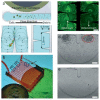
(a) Microfluidic device in which two PDMS channels facing each other are sealed together [14]. (b) Diagram of the chambers along with the channel dimensions. (c) Image of Arcella incubated with fluorescein diacetate in capture chambers. Adapted with permission from [14]. Copyright 2009 Copyright Royal Society of Chemistry.
Figure 4
Figure 4
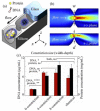
Percentage of cell lysis obtained in [18] for buffer resuspended cells, using Tris–HCl buffer, BPER, and lysozyme. (a) For different total flow rates (using the same flow rates of resuspended cell solution and buffer or lysis solution); (b) for different flow rate ratios (keeping constant total flow rate). Adapted with permission from [18]. Copyright 2020 Copyright Elsevier.
Figure 5
Figure 5
Scheme of the on-chip lysing and on-chip incubation of HL-60 cell with substrate developed in [20]. A fluorescence detector was located downstream of the mixing point, and an observation microscope sat over the intersection. Adapted with permission from [20]. Copyright 2004 Copyright IEEE.
Figure 6
Figure 6
Fluorescence intensity of a single HeLa cell versus the time after the introduction of the lysis buffer shown in [28].
Figure 7
Figure 7
The microfluidic platform utilized in [33] encapsulates cells into droplets with lysis buffer for cell lysis.
Figure 8
Figure 8
Schematic generalization of a microfluidic device for mechanical lysis.
Figure 9
Figure 9
(a) The nanostructured mechanical filter utilized in [38]. (b) A schematic of the mechanical lysis portion of the device Adapted with permission from [38]. Copyright 2003 Royal Society of Chemistry.
Figure 10
Figure 10
(a) Image of the silica monolith utilized in [39] for mechanical cell lysis. (b) Histogram of pore size. Critical diameter for RBC hemolysis is marked with an arrow.
Figure 11
Figure 11
(a) Schematics of the chip for mechanical cell lysis chip with ultra-sharp nano-blade arrays utilized [40]. (b) Comparison of protein concentration between the developed mechanical cell lysis method and the conventional chemical lysis method. Adapted with permission from [40]. Copyright 2010 Royal Society of Chemistry.
Figure 12
Figure 12
Single-cell point constriction utilized in [41] for reagent-free cell lysis. (a) Cell being ruptured by the ultra-sharp edge of a round constriction. (b) A cell undergoing excessive rapid deformation through a point constriction. (c) Comparison between the results of lysates obtained from a device without any constriction or from a conventional chemical method.
Figure 13
Figure 13
The pump-on-chip cell disruption microfluidic chip utilized in [50]; (a) schematic of the device, (b) picture of the fabricated cell disruption microfluidic chip. (c) Schematic of the platform with the on-chip micropump, electromagnets. (d) Cells in the sample leaking through the gap between the channel corners and the PDMS membrane are pulverized by the steel balls. (e) The compressive stress makes cells deform. (f) Some cells are crushed down by the steel balls. Adapted with permission from [50]. Copyright 2017 AIP Publishing.
Figure 14
Figure 14
Design and concept of the sharp-edge-based acoustofluidic device for cell lysis utilized in [56]. (a) Schematic overview of the mechanism of the acoustofluidic lysis device. Sharp-edged structures are constructed on the sidewalls of the channels. (b) The device is composed of a serpentine channel with a large number of sharp-edged structures, an acoustic transducer, and a thin glass substrate. (c) Comparison of the cell density downstream and upstream of the channel. Image (d) upstream and (e) downstream the channel. Adapted with permission from [56]. Copyright 2019 Royal Society of Chemistry.
Figure 15
Figure 15
Schematic generalization of a microfluidic device for mechanical lysis.
Figure 16
Figure 16
The schematic of the micro-electroporation chip is utilized in [65]. Cells in the region between the salt bridges experience an electric field. Adapted with permission from [65]. Copyright 2007 American Chemical Society.
Figure 17
Figure 17
(a) Sketch of a simple flow-through device for continuous electrical lysis of cells utilized in [67]. (b) Top view of the device. (c) An alternative inlet/outlet design for reducing the flow in comparison with that in (b), for a clear observation of cell lysis utilized in [67]. Cells in the region between the salt bridges experience an electric field.
Figure 18
Figure 18
Experimental procedures for cell patterning utilized in [69].
Figure 19
Figure 19
(a) Schematic of the magnetic bead setup utilized in [72]. The electromagnets generate a magnetic field, which rolls magnetic beads across the chip surface. (b) The beads are used to push the cells into position above the transistor. (c) An MCF-7 cell (red arrow) is moved from left to right by a bead (black arrow) to a position over a set of nanowires. (d) An HT-29 cell (blue arrow) is moved from left to right by a bead (black arrow) and positioned over a nanoribbon. Adapted with permission from [72]. Copyright 2013 Royal Society of Chemistry.
Figure 20
Figure 20
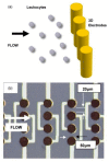
Three-dimensional cylindrical electrodes utilized in [75]. (a) Sketch of leukocytes approaching a singe row of electrode. The height of each electrode is 50 m. (b) The diameter of each electrode is 50 µm with spacing between them 20 µm. The height of each electrode is 50 µm. Adapted with permission from [75]. Copyright 2006 Elsevier.
Figure 21
Figure 21
Schematics of a micro electroporation device with only one set of electrodes for cell lysis utilized in [76]. Adapted with permission from [76]. Copyright 2006 Royal Society of Chemistry.
Figure 22
Figure 22
Schematic of the electrical lysis part and co-flow droplet generation part of the microfluidic device utilized in [74]. Adapted with permission from [74]. Copyright 2016 AIP Publishing.
Figure 23
Figure 23
Schematic representation of the working mechanism of the laser lysis in microfluidics.
Figure 24
Figure 24
Thermal lysis in a microfluidic device.
Figure 25
Figure 25
Schematic representation of the integrated microfluidic system (adopted from [95]). The microelectrodes deposited on the lower substrate act as driving elements, while the ones on the shielding channel are for the mixing of samples. 1–glass substrate, 2–micro heater, 3–integrated temperature sensor, 4–cover slide, 5–micro lysis reactor, 6–PCR reagent injection, 7–primer injection, 8–mixture reservoir, 9–mixer, 10–micro PCR camber.
Figure 26
Figure 26
Representation (a) and a photograph (b) of the integrated microfluidic system utilized in [101]. A metal heating unit with a hexagonal shape was embedded in a bottom layer of polydimethylsiloxane and a hexagonal metal heating unit was heated at a specified magnetic field. Adapted with permission from [101]. Copyright 2010 Royal Society of Chemistry.
Figure 27
Figure 27
Overview of the TSAW lysis device utilized in [104]. The lysis chip consists of a PDMS microchannel plasma-bonded to a lithium niobate (LiNbO3) substrate with an interdigitated transducer (IDT) adjacent to the microchannel to generate traveling surface acoustic waves. Bacteria suspension was flown through the microchannel (a) the bacteria suspension was exposed to a TSAW field (b) and the lysate for further analysis were collected (c). Adapted with permission from [104]. Copyright 2019 Royal Society of Chemistry.
Figure 28
Figure 28
Design of the electrochemical cell lysis devices utilized in [109]. (a) Cross-sectional and top-down views of the micro-devices. Cathode and anode chambers were separated by an ion exchangeable polymer diaphragm. (b) Photographs of the same microdevice. Adapted with permission from [109]. Copyright 2010 Royal Society of Chemistry.

Similar articles

Cited by

References

    1. Nguyen N., Wereley S. Fundamentals and Applications of Microfluidics. Artech House Publishing; Norwood, MA, USA: 2007.
    1. Islam M.S., Aryasomayajula T.A., Selvaganapathy P.R. A Review on Macroscale and Microscale Cell Lysis Methods. Micromachines. 2017;8:83. doi: 10.3390/mi8030083. - DOI
    1. Gao D., Jin F., Zhou M., Jiang M. Recent advances in single-cell manipulation and biochemical analysis on microfluidics. Analyst. 2019;17:1533–1547. doi: 10.1039/C8AN01186A. - DOI - PubMed
    1. Nandagopal M.S.G., Nakkeeran E., Prasanna V.R., Selvaraju N.N. Advance Microfluidic Approach over Conventional Batch and CTR for Improving the Efficiency of E-coli Cell Lysis by CuO Nanoparticles. Int. J. Chem. React. Eng. 2016;15:20160105. doi: 10.1515/ijcre-2016-0105. - DOI
    1. Yu F., Hunziker W.W., Choudhury D. Engineering Microfluidic Organoid-on-a-Chip Platforms. Micromachines. 2019;10:165. doi: 10.3390/mi10030165. - DOI - PMC - PubMed

LinkOut - more resources