Review
. 2021 Apr 26;11(5):1117.
doi: 10.3390/nano11051117.

Hybrid Nanocomposite Thin Films for Photovoltaic Applications: A Review

Affiliations
Review

Hybrid Nanocomposite Thin Films for Photovoltaic Applications: A Review

Marcela Socol et al. Nanomaterials (Basel). .

Abstract

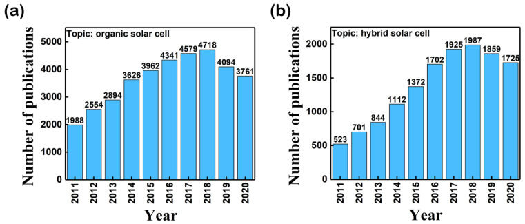
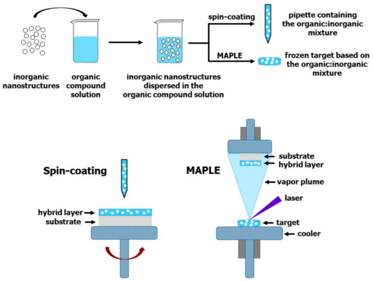
Continuing growth in global energy consumption and the growing concerns regarding climate change and environmental pollution are the strongest drivers of renewable energy deployment. Solar energy is the most abundant and cleanest renewable energy source available. Nowadays, photovoltaic technologies can be regarded as viable pathways to provide sustainable energy generation, the achievement attained in designing nanomaterials with tunable properties and the progress made in the production processes having a major impact in their development. Solar cells involving hybrid nanocomposite layers have, lately, received extensive research attention due to the possibility to combine the advantages derived from the properties of both components: flexibility and processability from the organic part and stability and optoelectronics features from the inorganic part. Thus, this review provides a synopsis on hybrid solar cells developed in the last decade which involve composite layers deposited by spin-coating, the most used deposition method, and matrix-assisted pulsed laser evaporation, a relatively new deposition technique. The overview is focused on the hybrid nanocomposite films that can use conducting polymers and metal phthalocyanines as p-type materials, fullerene derivatives and non-fullerene compounds as n-type materials, and semiconductor nanostructures based on metal oxide, chalcogenides, and silicon. A survey regarding the influence of various factors on the hybrid solar cell efficiency is given in order to identify new strategies for enhancing the device performance in the upcoming years.

Keywords: MAPLE; conjugated polymers; hybrid nanocomposite films; hybrid photovoltaic cells; inorganic nanostructures; spin-coating.


Conflict of interest statement

The authors declare no conflict of interest.

Figures

Figure 1
Figure 1
A timeline chart of the best research cell efficiencies for different photovoltaic technologies from 1976 to present according to the National Renewable Energy Laboratory (NREL) [7]. This plot is courtesy of the National Renewable Energy Laboratory, Golden, CO, USA.
Figure 2
Figure 2
The number of the scientific publications referring to the topic (a) “organic solar cell” and (b)“hybrid solar cell” published between 2011 and 2020 (source: web of science [37]).
Figure 3
Figure 3
SEM images of ZnO (af) and CuO (g,h) nanostructures with various morphologies prepared by wet and dry techniques. (a) reprinted with permission from [44]. Copyright 2020 Elsevier. (b,d) reprinted with permission from [45]. (c) reprinted with permission from [46]. Copyright 2013 Elsevier. (e,g) reprinted with permission from [47]. Copyright 2020 Elsevier. (f) reprinted with permission from [48]. Copyright 2016 Elsevier. (g) reprinted with permission from [49]. Copyright 2015 AIP Publishing.
Figure 4
Figure 4
Schematic illustration of the steps involved in the deposition of organic:inorganic hybrid composite layers by spin-coating and MAPLE techniques.
Figure 5
Figure 5
Optical absorbance spectra of hybrid films based on (a) P3HT:PCBM:ZnO, (b) P3HT:PCBM:TiO2, and (c) P3HT:PCBM:ZnO:TiO2 blends with various weight ratios: 1:1:0, 1:0.75:0.25, 1:0.50.0.50, 1:0.25:0.75, 1:0:1 for blends based on ZnO nanoparticles (a) or TiO2 nanoparticles (b) and 1:1:0:0, 1:0.75:0.125:0.125, 1:0.50:0.25:0.25, 1:0.25:0.375:0.375, 1:0:0.50:0.50 for blends based on a ZnO and TiO2 nanoparticles mixture (c). Reprinted with permission from [94]. Copyright 2015 AIP Publishing.
Figure 6
Figure 6
UV–VIS absorption spectra of hybrid films based on P3HT:PCBM:CuO blends with various weight ratios, the amount of CuO nanoparticles increasing from bottom to top: 1:0.8:0.0 (S0), 1:0.8:0.01 (S1), 1:0.8:0.02 (S2), 1:0.8:0.03 (S3), 1:0.8:0.04 (S), and 1:0.8:0.05 (S5). Reprinted with permission from [184]. Copyright 2019 Elsevier.
Figure 7
Figure 7
(a) J-V characteristics under illumination of the PV cells fabricated with hybrid films based on P3HT:CdSe or PCPDTBT:CdSe blends. Inset: schematic representation of the PV architecture. (b) EQE spectra of the corresponding solar cells. Reprinted with permission from [197]. Copyright 2011 Elsevier.
Figure 8
Figure 8
(a) J–V characteristics and (b) EQE spectra of PV cells fabricated with hybrid layers based on PTB7:PCBM:CdS blends with different weight ratio of CdS nanoparticles. Reprinted with permission from [121]. Copyright 2016 Elsevier.
Figure 9
Figure 9
(a) Energy levels of PBDB-T, Cu2S and ITIC. (b) Schematic representation of the PV architecture. (c) J–V characteristics under illumination of the PV cells fabricated with hybrid films based on PBDB-T:Cu2S:ITIC blends with different weight ratios of Cu2S nanocrystals. Reprinted with permission from [226]. Copyright 2019 Elsevier.
Figure 10
Figure 10
Energy band alignment in the devices developed with hybrid films based on P3HT:PC61BM blends and (a) p-Si nanoparticles or (b) n-Si nanoparticles. (c) J–V curves for the reference, n-Si and p-Si nanoparticles incorporated devices and their photo-conversion efficiency. Reprinted with permission from [104]. Copyright 2018 Elsevier.
Figure 11
Figure 11
TEM images of PCPDTBT:pyridine-capped CdSe blends deposited by (ac) spin-casting using trichlorobenzene as solvent and (df) RIR-MAPLE using trichlorobenzene as primary solvent. Reprinted with permission from [65]. Copyright 2015 Elsevier.
Figure 12
Figure 12
(a) J–V curves of PV cells developed on hybrid layers based on PCPDTBT:pyridine-capped CdSe blends with different CdSe loading, the films being deposited by RIR-MAPLE. (b) EQE of the corresponding solar cells. Reprinted with permission from [65]. Copyright 2015 Elsevier.
Figure 13
Figure 13
Optical properties, (a,b) transmittance and (c,d) photoluminescence, of MAPLE deposited hybrid films based on ZnPc:ZnO (a,d) or CoPc:C60:ZnO (b) in both hybrid type being varied the amount of ZnO nanoparticles: 1:0.15 (P1), 1:0.35 (P2) and 1:0.55 (P3) for blends based on ZnPc (a,d) and 1:1:0 (P0), 1:1:0.25 (P1), 1:1:0.75 (P2), and 1:1:1 (P3) for blends based on CoPc (b). The emission spectrum of film based on ZnO nanoparticles deposited by MAPLE (c). (a,c,d) reprinted with permission from [44]. Copyright 2020 Elsevier. (b) reprinted from [64].
Figure 14
Figure 14
FESEM images of the MAPLE deposited thin films based on CoPc:C60:ZnO blends with various amount of ZnO nanoparticles: 1:1:0 (P0), 1:1:0.25 (P1), 1:1:0.75 (P2), and 1:1:1 (P3). Insets: EDX spectra and weight and atomic percentages of the elements in the corresponding samples. Reprinted from [64].
Figure 15
Figure 15
J-V characteristics of the structures developed on the MAPLE deposited layers based on (a) ZnPc:ZnO or (c) CoPc:C60:ZnO blends, in both hybrid type being varied the amount of ZnO nanoparticles: 1:0.15 (P1), 1:0.35 (P2) and 1:0.55 (P3) for blends based on ZnPc (a) and 1:1:0 (P0), 1:1:0.25 (P1), 1:1:0.75 (P2), and 1:1:1 (P3) for blends based on CoPc (c). Schematic representation of the devices involving MAPLE deposited layers based on ZnPc:ZnO (b) or CoPc:C60:ZnO (inset c). (a,b) reprinted with permission from [44]. Copyright 2020 Elsevier. (c) reprinted from [64].

References

    1. Grätzel M. Powering the planet. Nature. 2000;403:363. doi: 10.1038/35000273. - DOI
    1. Solar Power, Origami-Style. [(accessed on 11 January 2021)]; Available online: https://www.nasa.gov/jpl/news/origami-style-solar-power-20140814.
    1. Ohl R.S. Light-Sensitive Electric Device Including Silicon. 2443542. U.S. Patent. 1948 Jun 15;
    1. Chapin D.M., Fuller C.S., Pearson G.L. A new Silicon p-n junction photocell for converting solar radiation into electrical power. J. Appl. Phys. 1954;25:676–677. doi: 10.1063/1.1721711. - DOI
    1. Chapin D.M., Fuller C., Pearson G. Solar Energy Converting Apparatus. 2780765. U.S. Patent. 1957 May 5;

LinkOut - more resources