Review
. 2021 May:124:112057.
doi: 10.1016/j.msec.2021.112057. Epub 2021 Mar 25.

Recent advances in bioprinting technologies for engineering cardiac tissue

Affiliations
Review

Recent advances in bioprinting technologies for engineering cardiac tissue

Tarun Agarwal et al. Mater Sci Eng C Mater Biol Appl. 2021 May.

Abstract

Annually increasing incidence of cardiac-related disorders and cardiac tissue's minimal regenerative capacity have motivated the researchers to explore effective therapeutic strategies. In the recent years, bioprinting technologies have witnessed a great wave of enthusiasm and have undergone steady advancements over a short period, opening the possibilities for recreating engineered functional cardiac tissue models for regenerative and diagnostic applications. With this perspective, the current review delineates recent developments in the sphere of engineered cardiac tissue fabrication, using traditional and advanced bioprinting strategies. The review also highlights different printing ink formulations, available cellular opportunities, and aspects of personalized medicines in the context of cardiac tissue engineering and bioprinting. On a concluding note, current challenges and prospects for further advancements are also discussed.

Keywords: Bioprinting; Cardiac tissue engineering; Cardio-inductive microenvironment; Stem cells.


Conflict of interest statement

Conflict of Interest Statement

All authors declare no conflict of interest either among themselves or with any funding agency.

Figures
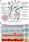
Figure 1
Figure 1
Cardiac anatomy. (A) Structure of the heart. (B) Layers of the myocardium. Reproduced from [16] with permission from Elsevier.
Figure 2
Figure 2
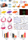
(A) Schematic illustration of the LAB setup and the process of transferring cells on a PEUU cardiac patch. (B) Spatially organized human MSCs (PKH26+, red) and HUVEC (CD31+, green) were observed within grid patterns of cardiac patches after 24 h of printing. (C) In vivo implantation of bioprinted cardiac patch in rat’s left anterior descending (LAD) ligation model. (D) Quantitative measurements of inner wall thickness in different groups: MIC (untreated LAD-ligation controls), MIP (LAD-ligation combined with untreated patch), MIX (patch with randomly seeded cell-co-culture), and LIFT (LAB-based cardiac patch with grid pattern). The inner wall thickness measurements showed no significant increase in the values for LIFT compared to MIP after 8 weeks of implantation. (E) Representative ventricular cross-sections from major infarcted regions in different groups. The sections were stained with Fast Green FCF and Sirius red for identifying the myocytes and collagen deposition respectively. The images highlighted in dotted square grids represent the Fast Green FCF and Sirius red-stained sections in border zone in different groups, indicating the extent of fibrosis. Reproduced with permission from [67].
Figure 3
Figure 3
(A) Visual representation of the bioprinting process. (B) Demonstration of bioprinting process for a cardiac patch by using 2 different bioinks, deposited as alternate fiber strands on PCL based 3D printed support. (C) Illustration of various experimental variations included in the study: CPC (only CPCs), Mix C/M (randomly mixed CPCs, MSCs, and VEGFs) and Pattern C/M (patterning of CPCs-containing (bioink 1) and MSCs and VEGF-containing (bioink 2) strands, alternatively). (D) Alternate pattern design of CPCs and MSCs in the bioprinted cardiac patch fabricated on PCL support structures (Scale 200 µm). (E) Masson’s Trichrome (MTC)-stained section of untreated MI group and those implanted with CPC, Mix C/M, and Pattern C/M patches (Scale 1 mm). (F) Immunohistochemistry-staining of infarcted regions in different groups against CD31. Assessment of (G) LV wall thickness and (H) fibrosis in various experimental groups after 8 weeks of implantation. (I) Quantification of vascularization in different groups, represented as number/mm2 area. Reproduced with permission from [69].
Figure 4
Figure 4
(A) Schematic representation of the SWIFT process. (B) (i) Large-scale microwell culture of iPSCs (scale 300 µm), (ii) harvest of approximately 2.5 ml volume of embryoid bodies (EBs), (iii) and an image of the compacted form of EBs to from organ building block (OBB) tissue matrix (Scale 200 µm). (C) Time-lapse images of 3D printing of a sacrificial writing ink (orange) in an EB matrix (Scale 1 mm). (D) Sacrificial ink embedded by 3D printing in an EB matrix (Scale 1 mm). (E) Perfusion system employed to assess tissue viability of EB tissue matrix after SWIFT process. (F) Live/dead staining analysis carried out for the EB tissue matrix after 12 h of culture with: (i) no channel configuration (ii) normoxic (21% O2) (iii) hyper-oxygenated (95% O2) media (iv) quantification of normalized viability under different perfusion strategies in the full tissue (sea green) and core region (dark green), as indicated by grid lined rectangles in (i) (ii) and (iii) (scale 500 µm). Reproduced with permission from [78].
Figure 5
Figure 5
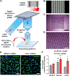
(A) A schematic illustration of the overall bioprinting process. First step involved differentiation of iPSCs into iPSC-CMs, which are further formulated with cardiac tissue-specific photocrosslinkable dECM-based bioink. Digital files for 3D constructs to be printed are designed and given as input to a DLP-based bioprinters to print the microarchitecture constructs within seconds. (B) Pattern present in the digital file as input to the DLP-based bioprinter. (C) Gross morphology (scale 1 mm) and (D) microarchitecture (scale 200 µm) of the acellular bioprinted cardiac tissue construct by using DLP-based 3D bioprinter. (E) Immunohistochemical staining (α-actinin, actin) of cells in the constructs after 7 days of culture (scale 50 µm). Nucleus was stained with DAPI. (F) Gene expression profile cardiac specific markers (NK2 homeobox 5 (NKX2.5), myosin regulatory light chain 2 (MLC-2v), cardiac Troponin T (cTNT)) in the bioprinted constructs. Bioprinted collagen constructs were used as control for the study. Reproduced with permission from [55].
Figure 6
Figure 6
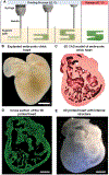
(A) A schematic illustration of FRESH process of bioprinting. Hydrogel (green) is deposited and crosslinked within thermo-reversible gelatin support bath (yellow) at 22 °C. Post-printing the temperature was raised to 37 °C to release the final structure and melt gelatin. (B) Representative dark-field image of an embryonic chick heart explant (scale 1 mm). (C) 3D CAD model of a cross section of the embryonic heart with internal trabecular features, generated based on confocal imaging data. (D) Representative image of cross section of the bioprinted heart with fluorescent alginate (green), with clear visualization of internal trabecular features of the 3D CAD model, the 3D CAD model of heart was scaled by factor of 10 to meet the printing resolution of the printer (scale 1 cm). (E) A dark-field image of the translucent bioprinted heart (scale 1 cm). Reproduced with permission from [87].
Figure 7
Figure 7
(A) Schematic representation of Kenzan method of scaffold-free bioprinting for the fabrication of 3D cardiac patch. First step involved the formation of cardiac spheroids in ultra-low attachment 96 well plates. Next the design of the 3D construct is prepared and provided to a 3D bioprinter. The 3D bioprinter picks up a cardiac spheroid and places onto a needle array. The cardiac cell spheroids are allowed to fuse to form 3D bioprinted cardiac patch. The 3D cardiac patches are removed and cultured to promote maturation. (B) Histological analysis of 3D bioprinted cardiac constructs: Hematoxylin and eosin staining (H&E) and MTC staining (scale 100 µm). (C) Immunohistochemistry analysis of 3D bioprinted cardiac constructs cTNT, vimentin, and CD31 (scale 100 µm). (D) In vivo implantation of 3D bioprinted cardiac construct on anterior surface of rat heart. The highlighted image within dashed lines represents the anterior aspect of the explanted heart. (E) Histological analysis of the implanted 3D bioprinted cardiac construct by H&E and MTC staining (scale 400 µm). (F) Immunohistology analysis of implanted bioprinted constructs stained for human nuclear antigen (HNA), Wheat Germ Agglutinin (WGA), and DAPI (scale 40 µm). The dotted line indicates the border between native rat myocardium and 3D bioprinted cardiac construct. White arrow indicates the integration of the bioprinted cardiac construct with the native rat myocardium. Reproduced with permission from [35].
Figure 8
Figure 8
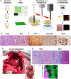
(A) Schematic workflow applied by Noor and colleagues. Briefly, after biopsy, personalized hydrogels and iPSCs – differentiated into CMs and ECs – were used to produce bioinks. The bioinks were then 3D bioprinted to generate vascularized patches or complex scaffolds suitable to be transplanted back into the patient. (B) 3D personalized cardiac patches. (i) Schematic printing concept (ii) A digital model of the cardiac vascularized patch. (iii) 3D printed cardiac patch, where (iv) the blood vessels (CD31 in green) are closer to the cardiac tissue (actinin in pink). (v) In vivo cardiac implant. (vi) Sarcomeric actinin (red) and nuclei (blue) staining of sections from the explanted patch. (C) Representative image of the heart. (i) CAD model of the heart. (ii, iii) The printed heart within a support bath. (iv) The confocal image of the printed heart (CMs in magenta, ECs in orange) and (v) the cross-sections of the heart stained against sarcomeric actinin (green) and ECs (red). Reproduced with permission from reference [45].
Figure 9
Figure 9
In vitro characterization of the fabricated cardiac patches using coculture of iPSC-CMs, ECs, and MSCs with different patterns and in vivo long-term evaluation of the fabricated cardiac patches. (A) CAD model of 3D stretchable construct. (B) A schematic illustration of internal stress-induced morphing mechanism. (C) 1 day and (D) 7 days of cell culture (Scale: 200 μm). (E) Confocal microscope images of green fluorescent protein-transfected iPSC-CMs after 7 days (Scale: 100 μm). (F) Immunostaining images of EC distribution to indicate capillary formation using CD31 on the fabricated cardiac patches (Scale: 200 μm). Immunostaining images of cardiac Troponin I (cTnI, red) and von Willebrand factor (vWf, green) on (G) wave-patterned and (H) mesh-patterned cardiac patches. (I) Implantation of the cardiac patch into the mouse heart. (J) An optical image of a heart model with I/R MI after 4 months. (K) An optical image of the cellularized cardiac patch after 3 weeks of implantation. (L) H&E assessment image of the cellularized cardiac patch after 3 weeks, where yellow arrows indicate dense cell clusters (Scale 400 μm). (M) A confocal microscope image of green fluorescent protein-transfected iPSC-CMs after 3 weeks, where yellow arrows indicate high engraftment (Scale 100 μm). (N) Immunostaining image of cTnI (red) and vWf (green) of the cellularized cardiac patch after 3 weeks (Scale 100 μm). (O) H&E assessment image of the original MI heart (left) and the heart with the cardiac patch after 10 weeks (right). The yellow circles indicate infarction (Scale 800 μm). (P) Cardiac magnetic resonance images (cMRI) of the heart with the cardiac patch after 10 weeks. The locations of the heart and the patch are indicated (left), and the blood perfusion is highlighted (right). Reproduced with permission from [132].

References

    1. Benjamin EJ, Muntner P, Alonso A, Bittencourt MS, Callaway CW, Carson AP, Chamberlain AM, Chang AR, Cheng S, Das SR, Delling FN, Djousse L, Elkind MSV, Ferguson JF, Fornage M, Jordan LC, Khan SS, Kissela BM, Knutson KL, Kwan TW, Lackland DT, Lewis TT, Lichtman JH, Longenecker CT, Loop MS, Lutsey PL, Martin SS, Matsushita K, Moran AE, Mussolino ME, O’Flaherty M, Pandey A, Perak AM, Rosamond WD, Roth GA, Sampson UKA, Satou GM, Schroeder EB, Shah SH, Spartano NL, Stokes A, Tirschwell DL, Tsao CW, Turakhia MP, VanWagner LB, Wilkins JT, Wong SS, Virani SS, Heart Disease and Stroke Statistics—2019 Update: A Report From the American Heart Association, Circulation 139 (2019) e56–e528. 10.1161/CIR.0000000000000659. - DOI - PubMed
    1. Bergmann O, Bhardwaj RD, Bernard S, Zdunek S, Barnabé-Heider F, Walsh S, Zupicich J, Alkass K, Buchholz BA, Druid H, Jovinge S, Frisén J, Evidence for Cardiomyocyte Renewal in Humans, Science (80−. ) 324 (2009) 98–102. 10.1126/science.1164680. - DOI - PMC - PubMed
    1. Wilcken DEL, Physiology of the normal heart, Medicine (Baltimore) 38 (2010) 336–339. 10.1016/j.mpmed.2010.03.014. - DOI
    1. Shadrin IY, Allen BW, Qian Y, Jackman CP, Carlson AL, Juhas ME, Bursac N, Cardiopatch platform enables maturation and scale-up of human pluripotent stem cell-derived engineered heart tissues, Nat. Commun 8 (2017) 1825. 10.1038/s41467-017-01946-x. - DOI - PMC - PubMed
    1. Duan B, State-of-the-Art Review of 3D Bioprinting for Cardiovascular Tissue Engineering, Ann. Biomed. Eng 45 (2017) 195–209. 10.1007/s10439-016-1607-5. - DOI - PubMed

LinkOut - more resources