. 2021 Jun;22(6):183-190.
doi: 10.1002/acm2.13263. Epub 2021 May 5.

A calibration CT mini-lung-phantom created by 3-D printing and subtractive manufacturing

Affiliations

A calibration CT mini-lung-phantom created by 3-D printing and subtractive manufacturing

H Henry Guo et al. J Appl Clin Med Phys. 2021 Jun.

Abstract

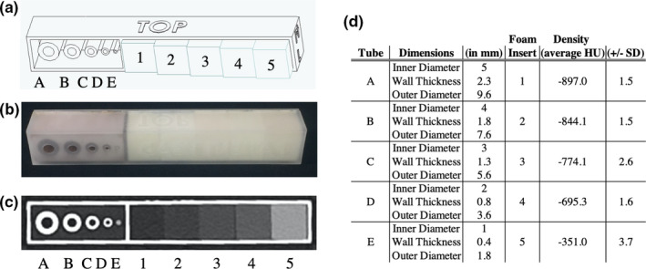
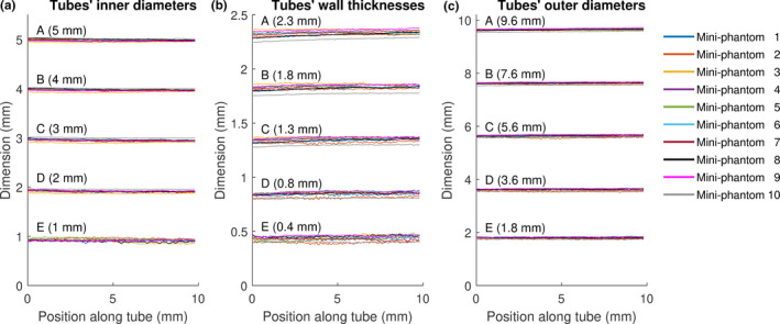
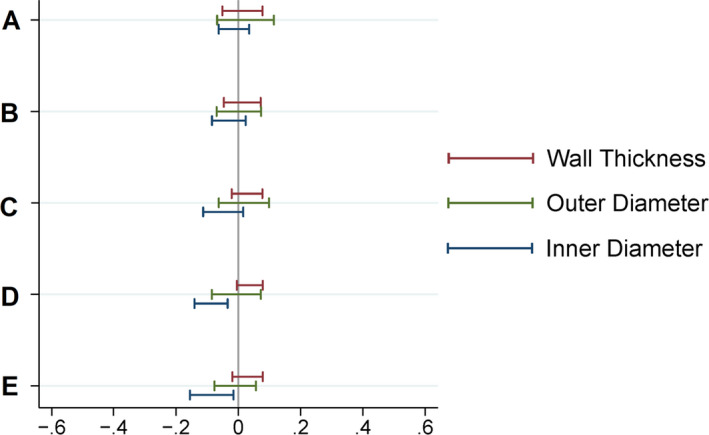
We describe the creation and characterization of a calibration CT mini-lung-phantom incorporating simulated airways and ground-glass densities. Ten duplicate mini-lung-phantoms with Three-Dimensional (3-D) printed tubes simulating airways and gradated density polyurethane foam blocks were designed and built. Dimensional accuracy and CT numbers were measured using micro-CT and clinical CT scanners. Micro-CT images of airway tubes demonstrated an average dimensional variation of 0.038 mm from nominal values. The five different densities of incorporated foam blocks, simulating ground-glass, showed mean CT numbers (±standard deviation) of -897.0 ± 1.5, -844.1 ± 1.5, -774.1 ± 2.6, -695.3 ± 1.6, and -351.0 ± 3.7 HU, respectively. Three-Dimensional printing and subtractive manufacturing enabled rapid, cost-effective production of ground-truth calibration mini-lung-phantoms with low inter-sample variation that can be scanned simultaneously with the patient undergoing lung quantitative CT.

Keywords: 3D printing; airway measurements; calibration; phantoms; quantitative CT.


Conflict of interest statement

No conflicts of interest.

Figures

Fig. 1
Fig. 1
The calibration CT mini‐lung‐phantom with simulated airway tubes and ground‐glass densities. (a) Computer‐aided design schematic of the mini‐lung‐phantom, showing five tubes with designed nominal 5, 4, 3, 2, 1mm inner diameters, labeled as tube A, B, C, D, E, respectively, and five polyurethane foam inserts simulating increasing ground‐glass densities in the phantom, labeled as inserts 1, 2, 3, 4, 5, with nominal 0.096, 0.160, 0.240, 0.320, and 0.641 g/cm3 densities, respectively. (b) Photograph of an external calibration mini‐lung‐phantom. (c) Axial clinical CT Image of the phantom, demonstrating tubes A‐E and foam block inserts 1–5. (d) Specifications of mini‐lung‐phantoms with nominal dimensions: inner diameter (ID), wall thickness (WT), and outer diameter (OD) of tubes A‐E, and CT HU densities of foam block inserts 1–5 as listed.
Fig. 2
Fig. 2
Micro‐CT and clinical CT images of the mini‐lung‐phantom and dimensional measurements of its simulated airways. (a) Close‐up photograph of the five tubes A, B, C, D, and E in a mini‐lung‐phantom. (b) Axial micro‐CT image of the five tubes, with designed nominal inner diameters of 5, 4, 3, 2, 1 mm. (c) Axial clinical CT image of the five tubes. Note that the smallest tube E with 1 mm ID is poorly resolved by the clinical CT scanner. (d) Schematic of YACTA analysis of tube dimensions from micro‐CT, with pins denoting centerlines.
Fig. 3
Fig. 3
Micro‐CT measurements of (a) inner diameters, (b) wall thicknesses, and (c) outer diameters of every tube (A‐E) plotted along tubes’ long axis. The design specified nominal dimensions of ID, WT, and OD of each tube are provided in parentheses.
Fig. 4
Fig. 4
95% confidence / 99% coverage tolerance intervals for deviation from inner diameter, wall thickness, and outer diameter nominal values based on micro‐CT measurements of five tubes (A‐E) of all 10 mini‐lung‐phantoms. Such intervals are calculated to contain 95% confidence 99% of all future observations. Nonparametric (Hahn‐Meeker method) intervals were calculated. The tolerance intervals for all parameters are well within ±0.2 mm.
Fig. 5
Fig. 5
Simulated use of calibration mini‐phantom in clinical CT. Demonstration photograph of the calibration mini‐lung‐phantom placed on top of an anthropomorphic thorax phantom, as an example placement of the mini‐lung‐phantom on the patient chest in clinical chest CT.

References

    1. Chen A, Karwoski RA, Gierada DS, Bartholmai BJ, Koo CW. Quantitative CT analysis of diffuse lung disease. Radiographics. 2020;40:28–43. - PubMed
    1. Galbán CJ, Han MK, Boes JL, et al, Computed tomography–based biomarker provides unique signature for diagnosis of COPD phenotypes and disease progression. Nat Med. 2012;18:1711–1715. - PMC - PubMed
    1. Bartholmai BJ, Raghunath S, Karwoski RA, et al, Quantitative computed tomography imaging of interstitial lung diseases. J Thorac Imaging. 2013;28:298–307. - PMC - PubMed
    1. Goris ML, Zhu HJ, Blankenberg F, Chan F, Robinson TE. An automated approach to quantitative air trapping measurements in mild cystic fibrosis. Chest. 2003;123:1655–1663. - PubMed
    1. Wu X, Kim GH, Salisbury ML, et al, Computed tomographic biomarkers in idiopathic pulmonary fibrosis. The future of quantitative analysis. Am J Respir Crit Care Med. 2019;199:12–21. - PubMed