

doi: 10.1107/S1600577521003325.
Epub 2021 Apr 27.
Synchrotron radiation and X-ray free-electron lasers (X-FELs) explained to all users, active and potential
Affiliations
- PMID: 33950010
- PMCID: PMC8127362
- DOI: 10.1107/S1600577521003325
Item in Clipboard
Synchrotron radiation and X-ray free-electron lasers (X-FELs) explained to all users, active and potential
J Synchrotron Radiat.
.
Abstract
Synchrotron radiation evolved over one-half century into a gigantic worldwide enterprise involving tens of thousands of researchers. Initially, almost all users were physicists. But now they belong to a variety of disciplines: chemistry, materials science, the life sciences, medical research, ecology, cultural heritage and others. This poses a challenge: explaining synchrotron sources without requiring a sophisticated background in theoretical physics. Here this challenge is met with an innovative approach that only involves elementary notions, commonly possessed by scientists of all domains.
Keywords: X-FEL; ponderomotive; relativity; synchrotron.
open access.
Figures
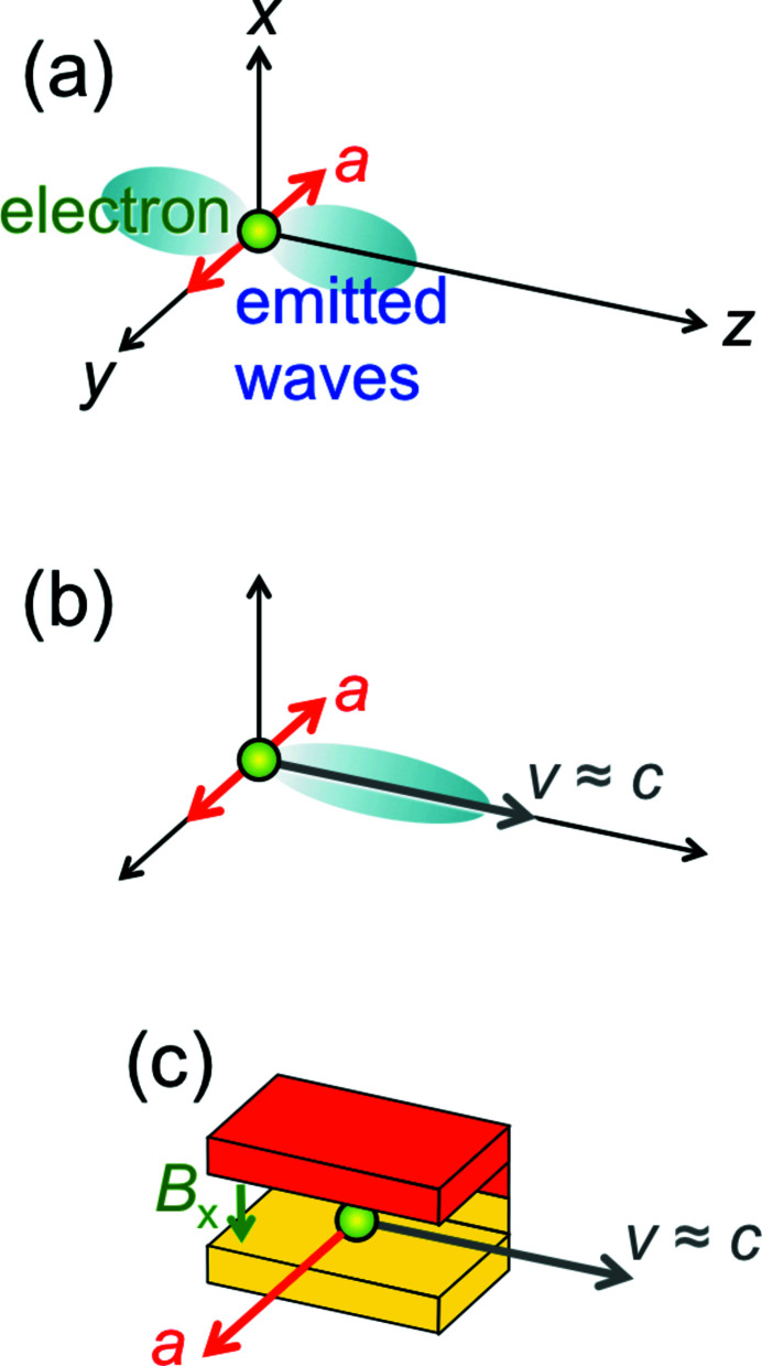
(a) Generic mechanism for the emission of electromagnetic radiation, including X-rays: an electron has an acceleration a in the transverse direction y and emits waves in the longitudinal direction z. (b) To exploit relativity and produce short X-ray wavelengths, we add a longitudinal velocity v close to the speed of light. (c) A practical way to implement the mechanism (b), using a ‘bending magnet’ (Margaritondo, 1988 ▸) with a magnetic field of magnitude B
x in the transverse x-direction, which causes a Lorentz force along y.
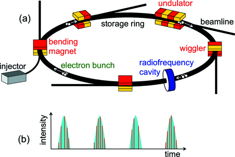
(a) Generic scheme of a synchrotron radiation facility with its accelerator (storage ring), the electron injector, a radiofrequency cavity, and X-ray sources of different types with their beamlines. The electrons circulate in the ring as regularly spaced bunches. (b) Each time an electron bunch passes through a source, it emits a pulse of radiation, which includes micropulses caused by individual electrons.
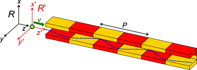
An ‘undulator’, a series of magnets of period P in the longitudinal direction, which forces the electrons to oscillate in a transverse direction (Margaritondo, 1988, 2002; Winick, 1995; Willmott, 2011; Mobilio et al., 2015; Bordovitsyn, 1999 ▸). Our relativistic description of the consequent undulator emission uses the reference frames R (laboratory and undulator) and R′ (electron).
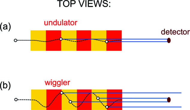
Top views explaining the emission bandwidths of undulators and wigglers. (a) During the passage of an electron through an undulator, the collimated beam of synchrotron radiation stays within a small-area detector, since the weak magnetic field causes only small lateral oscillations; this produces a long pulse. (b) The larger oscillations in a high-field wiggler bring the emitted beam in and out of the detector, producing a series of short pulses. Note, however, that the transition from undulators to wigglers is not sharply defined. Sometimes, the two terms are used interchangeably: for example, all the insertion devices of free-electron lasers are commonly called ‘undulators’.
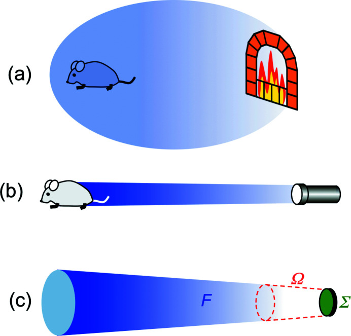
The notion of ‘brightness’ or ‘brilliance’. (a) A fireplace does not have high brightness since its emission, coming from a large area and being spread over a broad angular range, cannot bring much radiation into the zone of utilization. (b) A flashlight is more effective, i.e. it has high brightness. (c) We define the brightness (Margaritondo, 1988, 2002; Winick, 1995; Willmott, 2011; Mobilio et al., 2015; Bordovitsyn, 1999 ▸) by combining [equation (8)] the emitted flux F with the geometric parameters Ω (solid angle of emission) and Σ (source area).
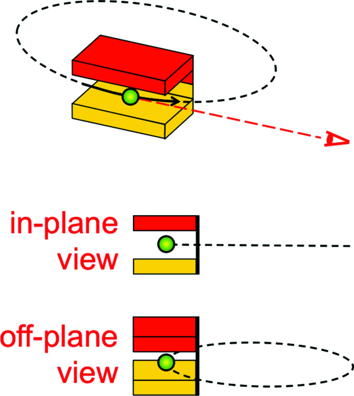
Polarization of synchrotron radiation. Top: a bending magnet causes the electrons to travel along a trajectory (solid line), which is a portion of a circle (dashed line). Middle: seen from the horizontal plane, the circle looks like a straight line, corresponding to linear polarization. Bottom: from a point of view slightly off the horizontal plane, the circle looks like an ellipse, and corresponds to elliptical polarization.
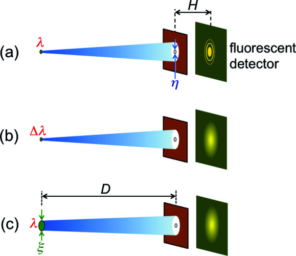
The notion of coherence, introduced using pinhole diffraction. (a) A point-like source emitting only one wavelength always produces a visible fringes pattern. (b) If the emission is not a single wavelength but a band, the fringes may be washed out. (c) Likewise, if the source is not a point but has a finite area, the fringes may not be visible.
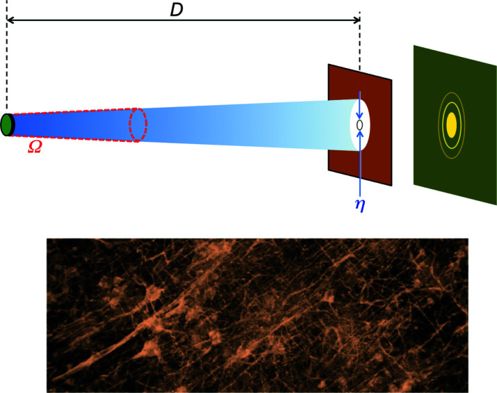
Top: the parameters used to define the ‘coherent power factor’ of equation (11). Bottom: an example of advanced radiology based on coherence – microscopic radiograph of a portion of a neuron network.
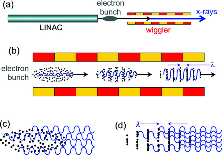
The main components of an X-FEL: (a) linear accelerator (LINAC) that produces relativistic electrons, and a long wiggler. (b) As a bunch of electrons travels along the wiggler, the interaction with the previously emitted waves progressively creates periodic electron ‘slices’ (‘microbunches’) with a period equal to the wavelength. The waves emitted by microbunched electrons (d), unlike those without microbunching (c), are correlated and cause optical amplification.
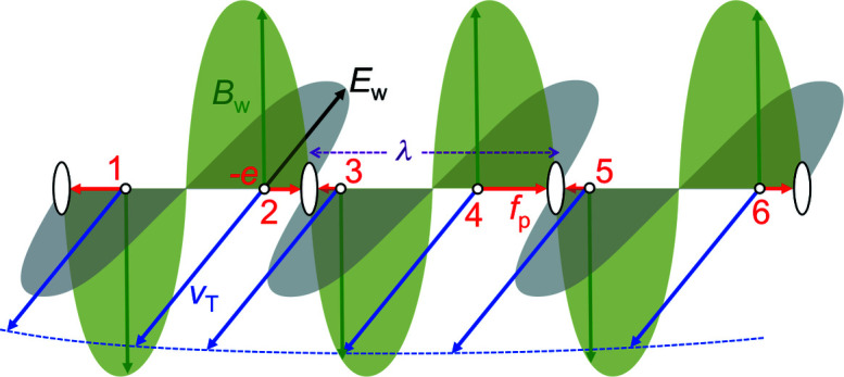
The ‘ponderomotive’ forces f
p, whose magnitudes are formally equivalent [equation (12)] to those of the Lorentz forces caused by the wave magnetic field B
w and by v
T, the transverse velocity of the wiggler-induced electron undulations. Such forces push some electrons (for example 2, 4, 6) in the forward longitudinal direction and others (1, 3, 5) backwards. But in both cases they accumulate in periodic microbunches, with periodicity equal to the wavelength.
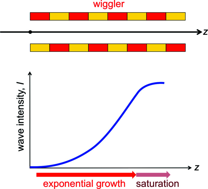
As the electrons enter and then travel along the wiggler (top), after a short initial phase the optical amplification causes an exponential increase of the wave intensity (bottom). But then the increase saturates, as explained in the text.
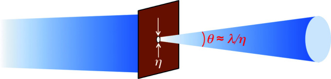
The ‘diffraction limit’: when trying to obtain a small-area source using a shield with a pinhole, diffraction increases the angular spread θ. This limits to ∼1 the increase of the coherent power factor of equation (11).
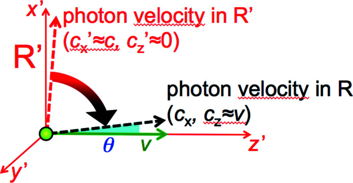
Analysis of the relativistic ‘beaming’.
References
-
- Allaria, E., Appio, R., Badano, L., Barletta, W. A., Bassanese, S., Biedron, S. G., Borga, A., Busetto, E., Castronovo, D., Cinquegrana, P., Cleva, S., Cocco, D., Cornacchia, M., Craievich, P., Cudin, I., D’Auria, G., Dal Forno, M., Danailov, M. B., De Monte, R., De Ninno, G., Delgiusto, P., Demidovich, A., Di Mitri, S., Diviacco, B., Fabris, A., Fabris, R., Fawley, W., Ferianis, M., Ferrari, E., Ferry, S., Froehlich, L., Furlan, P., Gaio, G., Gelmetti, F., Giannessi, L., Giannini, M., Gobessi, R., Ivanov, R., Karantzoulis, E., Lonza, M., Lutman, A., Mahieu, B., Milloch, M., Milton, S. V., Musardo, M., Nikolov, I., Noe, S., Parmigiani, F., Penco, G., Petronio, M., Pivetta, L., Predonzani, M., Rossi, F., Rumiz, L., Salom, A., Scafuri, C., Serpico, C., Sigalotti, P., Spampinati, S., Spezzani, C., Svandrlik, M., Svetina, C., Tazzari, S., Trovo, M., Umer, R., Vascotto, A., Veronese, M., Visintini, R., Zaccaria, M., Zangrando, D. & Zangrando, M. (2012). Nat. Photon. 6, 699.
-
- Amann, J., Berg, W., Blank, V., Decker, F. J., Ding, Y., Emma, P., Feng, Y., Frisch, J., Fritz, D., Hastings, J., Huang, Z., Krzywinski, J., Lindberg, R., Loos, H., Lutman, A., Nuhn, H. D., Ratner, D., Rzepiela, J., Shu, D., Shvyd’ko Yu Spampinati, S., Stoupin, S., Terentyev, S., Trakhtenberg, E., Walz, D., Welch, J., Wu, J., Zholents, A. & Zhu, D. (2012). Nat. Photon. 6, 693–698.
-
- Balzarotti, A., Bianconi, A., Burattini, E. & Strinati, G. (1974). Solid State Commun. 15, 1431–1434.
-
- Balzarotti, A., Piacentini, M. & Grandolfo, M. (1970). Lett. Nuov. Cim. 3, 15–18.
-
- Bathow, G., Freytag, E. & Haensel, R. (1966). J. Appl. Phys. 37, 3449–3454.
Grants and funding
LinkOut - more resources
Full Text Sources
Other Literature Sources
Miscellaneous
