Review
. 2021 Apr 21:2021:6659261.
doi: 10.1155/2021/6659261. eCollection 2021.

Real-Time Monitoring and Step-by-Step Guidance for Transapical Mitral Valve Edge-to-Edge Repair Using Transesophageal Echocardiography

Affiliations
Review

Real-Time Monitoring and Step-by-Step Guidance for Transapical Mitral Valve Edge-to-Edge Repair Using Transesophageal Echocardiography

Zhenyi Ge et al. J Interv Cardiol. .

Abstract

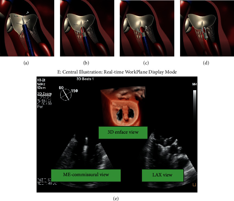
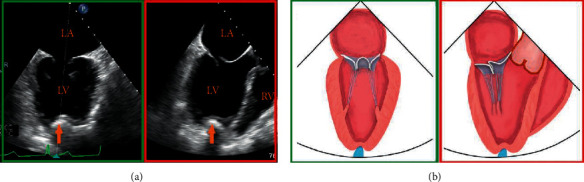
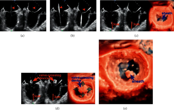
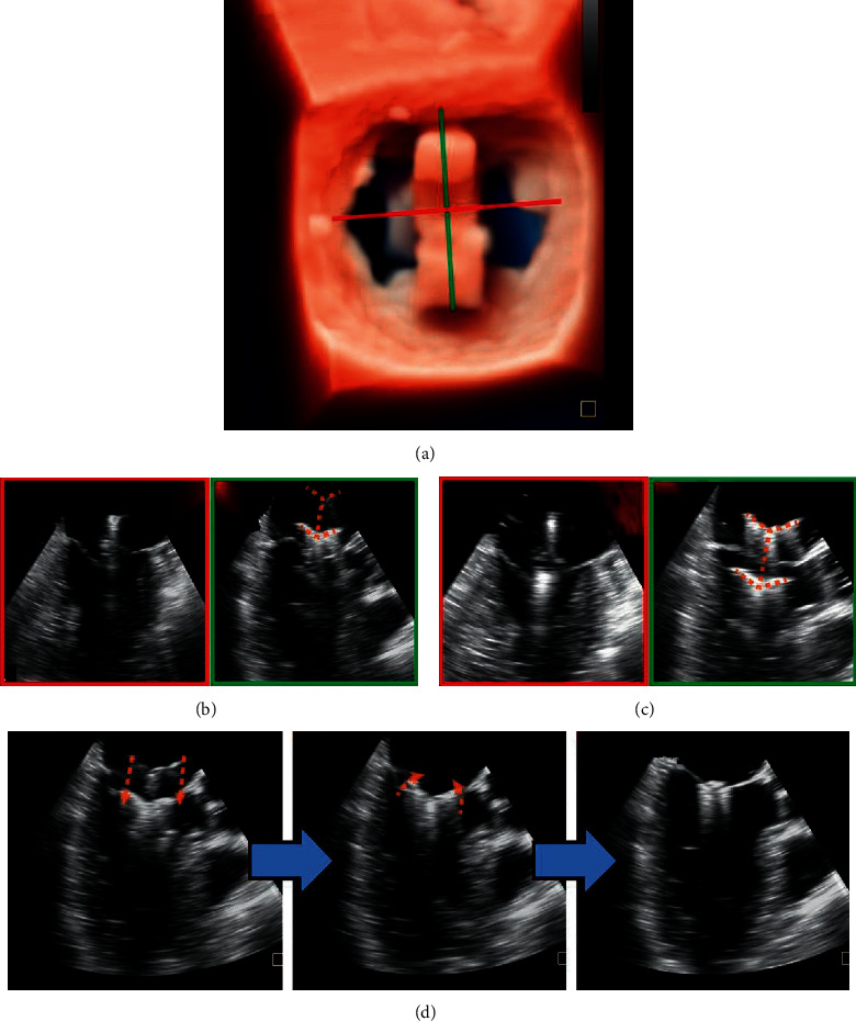
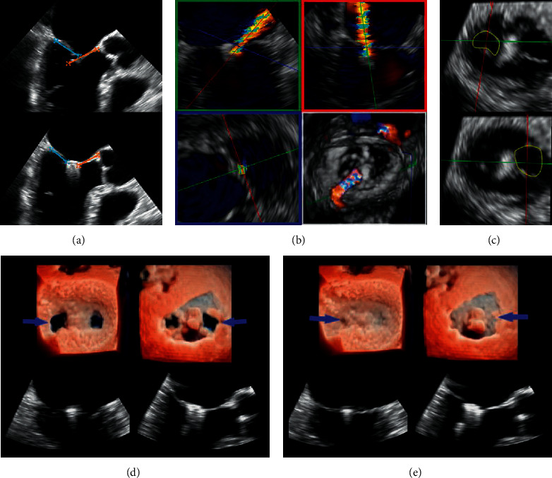
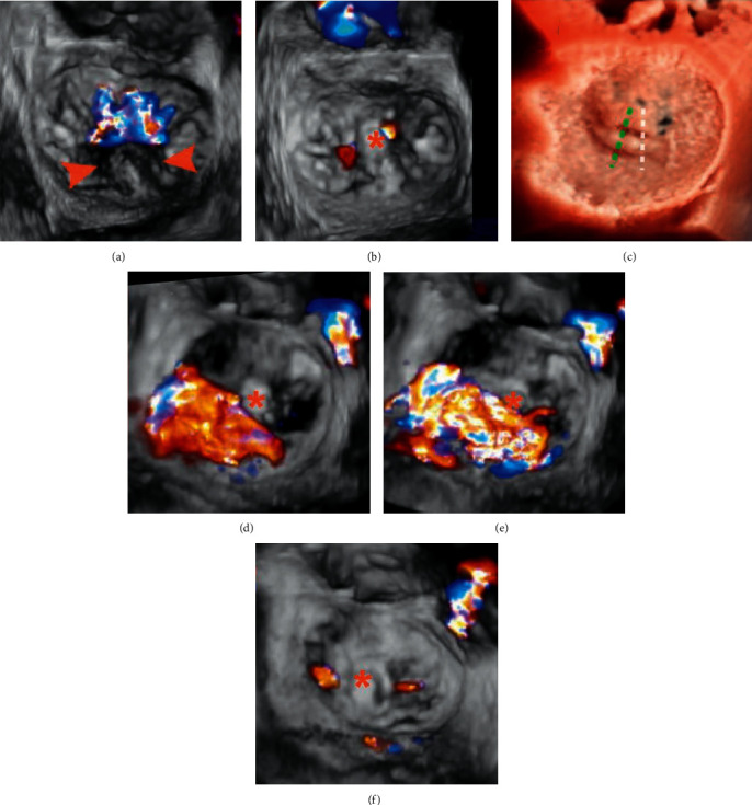
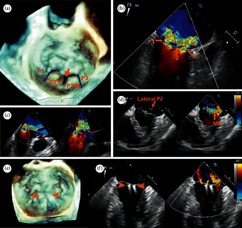
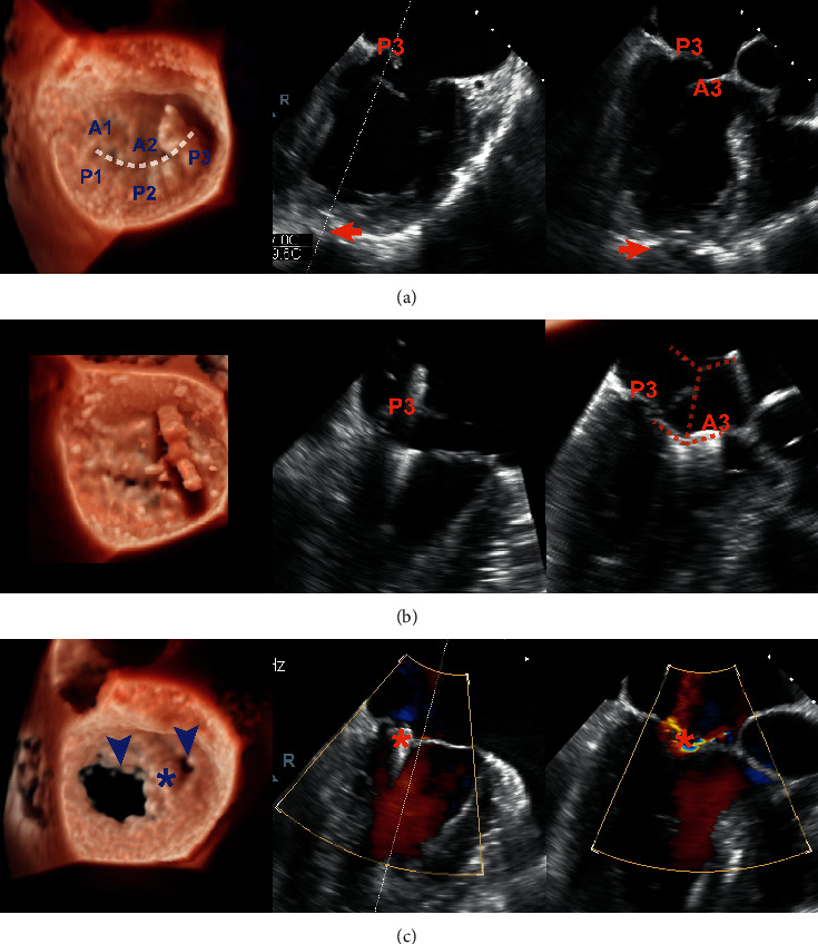
MitraClip edge-to-edge (E2E) repair system is the only transcatheter device recommended in the current guidelines for treating mitral regurgitation (MR). The percutaneous femoral venous transseptal access of MitraClip requires a complex steerable delivery system and may thus be technically complex to optimally position and deploy the clip onto the mitral valve. A transapical approach for E2E repair has been devised to treat MR for the ease of operation (ValveClamp system, Hanyu Medical Technology, Shanghai). The first-in-human study of ValveClamp has demonstrated its early feasibility and effectiveness for the treatment of patients with degenerative MR. Transesophageal echocardiography (TEE) is the only imaging modality required for intraoperative guidance of ValveClamp implantation. Successful implantation depends on accurate localization and orientation of the clamp and efficient intraoperative communication between the echocardiographer and the intervention team. Thus, the focus of this review is on elaborating how two-dimensional (2D) and three-dimensional (3D) TEE are used in clinical practice to guide ValveClamp implantation and it may facilitate the understanding of simplicity and safety of this novel procedure. We also describe the implementation of several novel advancements in 3D TEE imaging, which improve the confidence of image interpretation for intraoperative guidance and expedite implantation times.


Conflict of interest statement

Dr. Daxin Zhou and Dr. Wenzhi Pan are consultants for Hanyu Medical Technology. All the other authors have reported that they have no relationships relevant to the content of this paper to disclose.

Figures

Figure 1
Figure 1
The main steps of ValveClamp implantation. (a) A clamp is delivered to the left atrium. (b) The clamp is adjusted to the appropriate position, and the rear clamp is placed just under the leaflets, while the front clamp remains in the left atrium. (c) The front clamp is pulled back to capture the leaflets, and then the closed ring is moved forward to cover the ventricular end of the clamp arms, making them close to each other. (d) The clamp is released. Reproduced with permission from Pan et al. [10]. (e) Central illustration. The real-time workplane display mode simultaneously depicted X-plane views and 3D enface MV views, which is essential for navigating the main steps of ValveClamp implantation. ME, midesophageal; LAX, long-axis view.
Figure 2
Figure 2
Determination of an appropriate transapical puncture site. (a) The notch of the fingertip (orange arrow) is displayed simultaneously on X-plane views and schematic diagram (b), and oriented toward the center of the valve coaptation.
Figure 3
Figure 3
Transapical puncture and introducing the valve-crossing device. (a) X-plane view shows the guidewire enters LA through the mitral orifice (orange arrowhead). After that, a 6F guidewire is exchanged and advanced into LV and LA on a similar view. (b) Arrowhead. (c) 3D enface view + X-plane view show the introducer sheath is inserted coaxially to the LV and the insertion depth is approximately 3 cm (orange line). (d) The valve-crossing device is loaded into the introducer sheath and can be shifted in full directions (green arrows) within a reasonable scope of the MV orifice. (e) Coaxial advancement of the introducer sheath into the center of LA along the rod of valve-crossing device. AP: apex.
Figure 4
Figure 4
Advancement and adjustment of the clamp. 3D enface view (a) and X-plane view (b) show that the clamp is located in the center of the MV orifice and perpendicular to the MV closure line. The full length of the clamp arms (c) (orange dotted line) is seen in the long-axis view, and in the ME-commissural view, no clamp arms but the delivery rod should be seen. Next, the rear clamp is retracted into the LV, and the clamp orientation is reassessed with lowered gain settings (right: oblique perspective). (d) Leaflet Grasping.
Figure 5
Figure 5
Valve function assessment. (a) The length of leaflet insertion can be calculated, which equals the difference between the length of leaflets before and after grasping. (b) Planimetry of vena contracta (VC) area in a wall-hugging residual regurgitant jet. (c) Using multiplanar reformatting, planimetry of each residual orifice will allow for the calculation of cumulative MVA to exclude mitral valve stenosis. Each orifice should be measured in separate planes as they are not in the same plane. (d, e) The newly created double orifices are assessed by 3D zoom MV enface LA and LV view + X-plane view in the systolic frame (d) and diastolic frame (e).
Figure 6
Figure 6
3D CFD TEE assessment Patient A: (a) 3D TEE image with CFD showing a prolapse P2 segment (arrowheads) with a single wide central jet and (b) after implantation of 1 clamp, trivial residual mitral regurgitation is visible. Patient B: (c), (e), (f) in a case of noncentral bileaflet prolapse, prerelease 3D CFD TEE (d): early systolic frame, E: mid systolic frame) revealed a significant lateral residual MR following a central implantation of 1 clamp (c: white dotted line); after adjustment of position and regrasping of leaflets (c: green dotted line), two trivial residual MR jets are visible (f). This case highlighted the importance of precise clamp deployment for the maximal reduction of MR. Asterisks indicate clamps.
Figure 7
Figure 7
A 79-year-old male patient was referred for a history of chronic dyspnea (New York Heart Association functional class IV. (a) 3D enface view of the MV demonstrating a central cleft-like indentation with a prolapse lateral P2 (P2 (L) and a prolapse medial P2 (P2 (M). (b, c) 2D CDF TEE showing two dominant regurgitant jets (VCW: 7 mm and 6 mm, resp.) originating from the two prolapse P2 segments and a mild jet (VCW: 2 mm) from the central P2 indentation on bicommissural view and LVOT view. (d) Heart team decision was made on transapical ValveClamp implantation after his being deemed too high risk for surgical intervention. Implantation of the first clamp led to correction of the medial P2 segment, while the lateral P2 segment remained prolapse with a significant residual MR jet. (e) After implantation of the second clamp at the P2 segment, prolapse segments and regurgitant orifice were corrected and leaflet coaptation was preserved. (f) 2D CFD TEE showing mild residual jets (this case was diagnosed and treated before the TrueVue technique was commercially available).
Figure 8
Figure 8
Noncentral ValveClamp implantation and its effect in a patient with a P3 prolapse and flail. Left column: real-time 3D TEE TrueVue mode; middle and right column: ME-commissural view and ME-LAX view of X-plane imaging mode, respectively. (a) X-plane image (systolic frame) helped the operator to identify a proper site of puncture (arrow). (b) The process of leaflet capture using the clamp (orange dotted line). (c) 3D TEE (diastolic frame) demonstrating a large and a small MV orifice (arrowheads) and X-plane image (systolic frame) showing two trivial residual regurgitant jets after clamp release (asterisks).

Similar articles

Cited by

References

    1. Maisano F., Alfieri O., Banai S., et al. The future of transcatheter mitral valve interventions: competitive or complementary role of repair vs. replacement? European Heart Journal. 2015;36(26):1651–1659. doi: 10.1093/eurheartj/ehv123. - DOI - PubMed
    1. Hahn R. T. Transcathether valve replacement and valve repair. Circulation Research. 2016;119(2):341–356. doi: 10.1161/circresaha.116.307972. - DOI - PubMed
    1. Wunderlich N. C., Beigel R., Ho S. Y., et al. Imaging for mitral interventions. JACC: Cardiovascular Imaging. 2018;11(6):872–901. doi: 10.1016/j.jcmg.2018.02.024. - DOI - PubMed
    1. Geyer M., Sotiriou E., Tamm A. R., et al. Advanced protocol for three-dimensional transesophageal echocardiography guidance implementing real-time multiplanar reconstruction for transcatheter mitral valve repair by direct annuloplasty. Journal of the American Society of Echocardiography. 2019;32(10):1359–1365. doi: 10.1016/j.echo.2019.05.015. - DOI - PubMed
    1. Bushari L. I., Reeder G. S., Eleid M. F., et al. Percutaneous transcatheter edge-to-edge MitraClip technique: a practical “step-by-step” 3-dimensional transesophageal echocardiography guide. Mayo Clinic Proceedings. 2019;94(1):89–102. doi: 10.1016/j.mayocp.2018.10.007. - DOI - PubMed

MeSH terms

LinkOut - more resources