Comparative Study
. 2021 Aug;47(8):2310-2320.
doi: 10.1016/j.ultrasmedbio.2021.03.008. Epub 2021 May 11.

On the Relationship between Spatial Coherence and In Situ Pressure for Abdominal Imaging

Affiliations
Comparative Study

On the Relationship between Spatial Coherence and In Situ Pressure for Abdominal Imaging

Bofeng Zhang et al. Ultrasound Med Biol. 2021 Aug.

Abstract

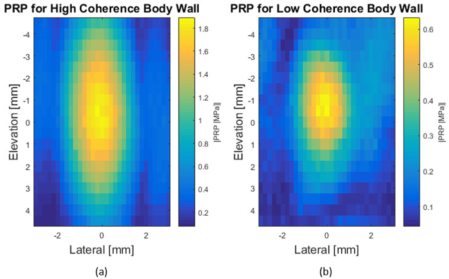
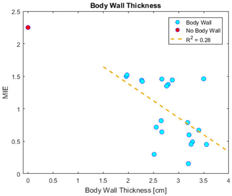
Tissue harmonic signal quality has been shown to improve with elevated acoustic pressure. The peak rarefaction pressure (PRP) for a given transmit, however, is limited by the Food and Drug Administration guidelines for mechanical index. We have previously demonstrated that the mechanical index overestimates in situ PRP for tightly focused beams in vivo, due primarily to phase aberration. In this study, we evaluate two spatial coherence-based image quality metrics-short-lag spatial coherence and harmonic short-lag spatial coherence-as proxy estimates for phase aberration and assess their correlation with in situ PRP in simulations and experiments when imaging through abdominal body walls. We demonstrate strong correlation between both spatial coherence-based metrics and in situ PRP (R2 = 0.77 for harmonic short-lag spatial coherence, R2 = 0.67 for short-lag spatial coherence), an observation that could be leveraged in the future for patient-specific selection of acoustic output.

Keywords: Abdominal ultrasound; In situ pressure; Measurement techniques; Mechanical index; Simulation; Spatial coherence; Tissue harmonic imaging.


Conflict of interest statement

Conflict of interest disclosure The authors declare no competing interests.

Figures

Figure 1:
Figure 1:
Experimental setup used to measure in situ PRP through a body wall sample. The transducer was fixed to a 3-axis translation stage. Pork body walls were secured against the transducer with two physical supports. The membrane hydrophone measuring pressure was submerged in a milk mixture that had attenuation matching that of human liver.
Figure 2:
Figure 2:
Experimental setup used to acquire channel data for spatial coherence values through a body wall sample. The pork belly and transducer were held in the same position relative to each other as in the PRP measurement setup shown in Figure 1. Data acquisition was performed with a customized toolset on the Sequoia scanner from a speckle generating phantom through a Tegaderm window at the base of the milk mixture container.
Figure 3:
Figure 3:
(a) Example clinical b-mode image of a pork belly sample used to segment the various tissue thicknesses and to estimate the sample attenuation. Layers shown are as follows: 1.5 mm skin, 6.9 mm fat, 4.6 mm muscle, 3.3 mm fat, and 8.2 mm muscle; The average attenuation estimate for the center line in the image was 0.61 dB/cm/MHz. (b) Photo of the corresponding pork belly sample mounted on to the transducer face.
Figure 4:
Figure 4:
Matching simulated in situ PRP/MIE waveforms, fundamental spatial coherence, and harmonic spatial coherence. (a) Pressure traces from the location of maximum pulse intensity integral. MIEs were: 0.87(yellow trace), 1.3 (orange trace) and 1.9 (purple trace). (b) Example spatial coherence curves at the axial focus of 5cm for the received signal at the fundamental frequency. (c) Example spatial coherence curves at the axial focus of 5cm for the received signal at the harmonic frequency when pulse inversion is simulated. The blue line shows the ideal case with pure speckle predicted by the VCZ theorem. The purple line is the spatial coherence computed from a simulation through speckle and no body wall. The red line is from an example body wall that was associated with a relatively high PRP (MIE = 1.3). The yellow curve is from an example body wall that was associated with a relatively low PRP (MIE = 0.87). All error bars represent the median and interquartile range for 20 adjacent simulated lines.
Figure 5:
Figure 5:
(a) The in situ PRP/MIE plotted against the fundamental SLSC values (2-way body wall simulations). (b) The in situ PRP/MIE plotted against the SLSC values from the 1-way body wall simulations. (c) The simulated in situ PRP/MIE plotted against the Harmonic SLSC values. The points are the median values, while the error bars represent the interquartile range across 20 simulated adjacent lines through the same body wall. The red point is the ideal case without a body wall. The blue points are various body walls. The dotted yellow line represents the linear regression line of best fit computed using the median values from the body wall samples (R2 =0.67, R2 =0.90, and R2 = 0.85).
Figure 6:
Figure 6:
Example experimentally measured spatial coherence curves at the axial focus of 6cm in the speckle phantom for the received channel data at the fundamental (a) and harmonic (b) frequency when pulse inversion is employed. The blue line shows the ideal speckle case predicted by the VCZ theorem. The purple points are the spatial coherence computed when the propagation path only has milk and a Tegaderm membrane on top of the speckle phantom. The red points are from an example pork belly that was associated with a relatively high PRP (MIE = 1.49). The yellow points are from an example pork belly that was associated with a relatively low PRP (MIE = 0.51). All error bars represent the median and interquartile range for the same transmit line when the speckle phantom is translated across 10 independent speckle locations.
Figure 7:
Figure 7:
(a) Coronal plane (elevation x lateral) map of the experimentally measured PRP magnitude at the axial depth of maximum PRP through the high coherence body wall in Figure 7. (b) plots the same metric as (a), but for the low coherence body wall in Figure 7. Note that these figures have different colorbars, with much lower PRPs in (b), suggesting considerable defocusing for the low coherence body wall case.
Figure 8:
Figure 8:
The experimentally measured in situ PRP/MIE plotted against the SLSC (a) and HSC (b) values computed by summing across the first 20 lags. The points are the median values, while the error bars represent the interquartile range across 10 speckle realizations from the same transmit line on the same pork belly section translated to different locations in the phantom. The red is the ideal case without a pork belly. The blue are various pork bellies. The dotted yellow line represents the linear regression line of best fit computed using the median values from all the pork belly samples. The R2 of the fit is 0.67 for SLSC and 0.77 for HSC.
Figure 9:
Figure 9:
The R2 value resulting from the linear regression line of best fit between experimentally measured spatial coherence and in situ PRP/MIE plotted vs. the maximum summation lag number used to compute SLSC and HSC. Red is the harmonic spatial coherence sum regression fit coefficient, while blue is the fundamental spatial coherence sum regression fit coefficient.
Figure 10:
Figure 10:
Pork belly thickness plotted with the corresponding MIE. Red is the case without a body wall present. Blue are the various pork body wall samples. The dotted yellow line is the linear regression line of best fit for all the pork belly samples. The regression coefficient is R2 = 0.28.

References

    1. Amador C, Song P, Meixner DD, Chen S, Urban MW. Improvement of Shear Wave Motion Detection Using Harmonic Imaging in Healthy Human Liver. Ultrasound in Medicine and Biology, 2016;42:1031–1041. - PMC - PubMed
    1. Asham EH, Kaseb A, Ghobrial RM. Management of Hepatocellular Carcinoma. Surgical Clinics of North America, 2013;93:1423–1450. - PubMed
    1. Bamber JC, Hill CR. Ultrasonic attenuation and propagation speed in mammalian tissues as a function of temperature. Ultrasound in Medicine and Biology, 1979;5:149–157. - PubMed
    1. Bradley C Mechanisms of Image Quality Improvement in Tissue Harmonic Imaging. In: AIP Conference Proceedings. Vol. 838. AIP, 2006. pp. 247–254.
    1. Bruix J, Sherman M. Management of hepatocellular carcinoma: An update. Hepatology, 2011;53:1020–1022. - PMC - PubMed

Publication types